TM-9-2320-260-34-2 - Page 285 of 863
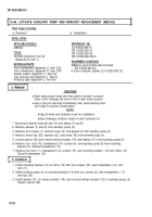
15-58. LIFTGATE CONTROL VALVE REPLACEMENT (M820A2)
THIS TASK COVERS:
a. Removal
b. Installation
INITIAL SETUP
APPLICABLE MODELS
M820A2
TOOLS
General mechanic’s tool kit
(Appendix B, Item 1)
MATERIALS/PARTS
Three Iockwashers (Appendix D, Item 238)
Cap and plug set (Appendix C, Item 6)
Anti seize tape (Appendix C, Item 50)
REFERENCES (TM)
LO 9-2320-260-12
TM 9-2320-260-10
TM 9-2320-260-34P-2
EQUIPMENT CONDITION
●
Parking brake set (TM 9-2320-260-10).
●
Liftgate lowered to ground level
(TM 9-2320-260-10).
●
Control linkage removed from control valve
(para. 15-55).
●
Drain hydraulic system (L0 9-2320-260-12).
a. Removal
CAUTION
1.
2.
3.
4.
5.
6.
7.
8.
●
Clean area around hoses and lines before removal to prevent
entry of dirt. Damage will occur if dirt or dust enters system.
●
Cap or plug all openings immediately after disconnecting lines
and hoses to prevent contamination.
NOTE
Tag all hydraulic lines for installation.
Have drainage container ready to catch hydraulic oil.
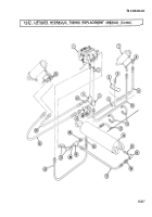
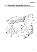
Disconnect hydraulic hoses (13) and (17) from control valve (3).
Disconnect hydraulic hoses (15) and (16) from two connectors (14).
Disconnect hydraulic hoses (11) and (12) from two tees (10).
Remove three nuts (9), screws (1), Iockwashers (2), and control valve (3) from main frame
mount (4). Discard Iockwashers (2).
Disconnect hydraulic lines (5) and (7) from adapter (6) and tee (8).
N0T E
Perform steps 6 through 8 if replacing control valve.
Remove two connectors (14), flow control valve (23), and nipple (22) from two tees (10).
Remove two tees (10) and nipples (21) from control valve (3).
Remove adapter (6), tee (8), nipple (20), and elbows (18) and (19) from control valve (3).
Perform steps 1 through 4 if installing new control valve.
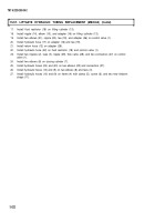
1. Wrap male threads on hydraulic hoses (5), (7), (11), (12), (13), and (17), connectors (14),
nipples (20), (21), and (22), adapter (6), and elbows (18) and (19) with antiseize tape.
2. Install elbows (18 and (19), nipple (20), tee (8), and adapter (6) on control valve (3).
3. Install two nipples (21) and tees (10) on control valve (3).
4. Install nipple (22), flow control valve (23), and two connectors (14) on two tees (10).
15-224
TM 9-2320-260-34-2
Back to Top

