TM-9-2320-260-34-2 - Page 57 of 863
TM 9-2320-260-34-2
14-4. DRIVER’S SEAT BASE MAINTENANCE
THIS TASK COVERS:
a. Removal
c. Installation
b. Inspection and Repair
INITIAL SETUP
APPLICABLE MODELS
REFERENCES (TM)
All
TM 9-2320-260-20
TOOLS
TM 9-2320-260-34P-1
General mechanic’s tool kit
EQUIPMENT CONDITION
(Appendix B, Item 1)
●
Driver’s seat removed (TM 9-2320-260-20).
• Driver’s seat cushion, backrest, frame, and seat
MATERIALS/PARTS
Four lockwashers (Appendix D, Item 235)
adjuster removed (TM 9-2320-260-20).
Eight lockwashers (Appendix D, Item 223)
GAA grease (Appendix C, Item 14)
a. Removal
1.
2.
3.
4.
5.
6.
7.
8.
9.
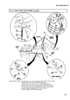
Turn crank (3)
counterclockwise to remove tension on spring (17).
Remove two nuts (2), screws (16), and shock absorber (18) from seat base (13) and top frame (l).
Remove four nuts (27), lockwashers (24), screws (26), and two brackets (25) from seat base (13).
Discard Iockwashers (24).
Remove spring (17) from seat base (13) and top frame (1).
Tag struts for installation.
Remove four nuts (5), lockwashers (6), screws ( 10), and lower strut (11) from top frame(1) and
seat base (13). Discard lockwashers (6).
Remove two nuts (9), lockwashers (8), torque rod (7), spring (22), sleeve (23), and spring (22) from
top frame (1) and upper strut (19). Discard lockwashers (8).
Remove two nuts (15), lockwashers (14), screws ( 12), and upper strut ( 19) from seat base (13).
Discard lockwashers (14).
Remove pin (20) from crank (3).
Remove crank (3) and washer (21) from swivel nut (4) and top frame (1).
14-2
Back to Top


