TM-9-2320-272-23-1 - Page 1178 of 1313
FIELD MAINTENANCE
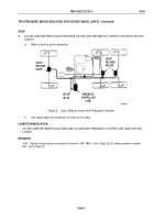
TWO PRESSURE MODES INDICATED WITH STEADY MODE LIGHTS
INITIAL SETUP:
Tools and Special Tools
Tool Kit, General Mechanic's: Automotive
(Volume 5, WP
0826, Table 1, Item 56)
Goggles, Industrial
(Volume 5, WP
0826, Table 1, Item 20)
Multimeter
(Volume 5, WP
0826, Table 1, Item 34)
Soap Solution
Test Set, Electronic Systems
(Volume 5, WP
0826, Table 1, Item 51)
Personnel Required
(2)
References
Point to Point Schematics
WP
0006
WP
0128
References (cont.)
Volume 2, WP
0322
Volume 3, WP
0352
Volume 3, WP
0481
Volume 3, WP
0482
Volume 3, WP
0487
Volume 5, WP
0805
Volume 5, WP
0806
Volume 5, WP
0809
Volume 5, WP
0810
Volume 5, WP
0811
Volume 5, WP
0812
Volume 5, WP
0813
Equipment Condition
Vehicle parked and engine shut down.
(TM
9-2320-272-10)
TROUBLESHOOTING PROCEDURE
TWO PRESSURE MODES INDICATED WITH STEADY MODE LIGHTS
NOTE
•
Conduct these malfunction tests if two pressure modes are indicated with steady mode
lights. This procedure will check for a problem with air lines between pneumatic controller
and wet tank, between quick release valves and pneumatic controller, and between quick
release valves and wheels. It will also check for a faulty filter element, water separator,
hub air seal, pneumatic controller, quick release valve, and CTIS wiring harness.
•
The Electronic Control Unit (ECU) has five pressure mode settings, with each setting
having a mode light. If, during programmed operation or after manually selecting a
pressure mode setting, two mode lights remain on, the CTIS will discontinue operation.
Two steady mode lights indicate that a particular inflate or deflate sequence has taken
longer than the programmed limits allow, and has shut the system off with air pressure
between the modes, indicated by lights. Use test box and follow the procedures below to
diagnose the system.
TM 9-2320-272-23-1
0144
0144-1
Back to Top


