TM-9-2320-272-23-1 - Page 26 of 1313
TABLE OF CONTENTS - Continued
Page No.
WP Sequence No.
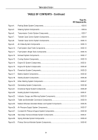
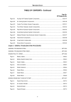
Figure 31.
Auxiliary Air-Powered System Components.
......................................................................
0003-47
Figure 32.
Air Venting System Components.
......................................................................................
0003-49
Figure 33.
Central Tire Inflation System Components.
........................................................................
0003-51
Figure 34.
Front Winch Hydraulic System Components.
.....................................................................
0003-52
Figure 35.
Rear Winch Hydraulic System Components.
.....................................................................
0003-53
Figure 36.
Dump Body Hydraulic System Components.
.....................................................................
0003-55
Figure 37.
Medium Wrecker Crane Hydraulic System Components.
..................................................
0003-57
Figure 38.
Hoist Action Components.
..................................................................................................
0003-58
Figure 39.
Crowd Action Components.
................................................................................................
0003-59
Figure 40.
Swing Action Components.
................................................................................................
0003-60
Chapter 2 - GENERAL TROUBLESHOOTING PROCEDURES
GENERAL TROUBLESHOOTING.
..............................................................................................................
WP 0004
GENERAL TROUBLESHOOTING INDEX.
..................................................................................................
WP 0005
ENGINE FAILS TO CRANK.
........................................................................................................................
WP 0006
Figure 1.
Battery Cables.
.....................................................................................................................
0006-2
Figure 2.
Battery Specific Gravity Test.
...............................................................................................
0006-3
Figure 3.
Starter Cables.
.....................................................................................................................
0006-4
Figure 4.
DCA Connection.
..................................................................................................................
0006-5
Figure 5.
Starter Solenoid.
...................................................................................................................
0006-6
Figure 6.
Starter Motor.
.......................................................................................................................
0006-6
Figure 7.
Starter Motor.
.......................................................................................................................
0006-7
Figure 8.
Starter Motor.
.......................................................................................................................
0006-8
ENGINE CRANKS BUT DOES NOT START.
.............................................................................................
WP 0007
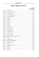
Figure 1.
Engine Stop Control.
............................................................................................................
0007-2
Figure 2.
Air Cleaner Indicator.
............................................................................................................
0007-2
Figure 3.
Engine Exhaust.
...................................................................................................................
0007-3
Figure 4.
Engine Exhaust.
...................................................................................................................
0007-4
TM 9-2320-272-23-1
v
Back to Top

