TM-9-2320-272-23-2 - Page 1163 of 1417
INSTALLATION
NOTE
Male pipe threads must be wrapped with antiseize tape before installation.
1.
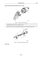
Install elbow (Figure 2, Item 5), fitting (Figure 2, Item 6), and spring brake pressure switch (Figure 2, Item 7)
on spring brake release control valve (Figure 2, Item 4).
2.
Connect two wires (Figure 2, Item 8) to spring brake pressure switch (Figure 2, Item 7).
3.
Install instrument cluster (Figure 2, Item 2) on instrument panel (Figure 2, Item 1) with eight screws
(Figure
2,
Item
3).
TM 9-2320-272-23-2
0308
0308-4
Back to Top


