TM-9-2320-272-23-2 - Page 1199 of 1417
REMOVAL
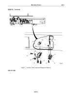
1.
Remove screw (Figure 1, Item 11) and outlet cable (Figure 1, Item 9) from auxiliary outlet socket
(Figure
1,
Item
12).
2.
Remove screw (Figure 1, Item 8), clamp (Figure 1, Item 14), and auxiliary outlet socket (Figure 1, Item 12)
from instrument panel (Figure 1, Item 13).
3.
Remove clip (Figure 1, Item 10) from instrument panel (Figure 1, Item 13).
4.
Disconnect wire (Figure 1, Item 1) from wire (Figure 1, Item 2).
5.
Remove four nuts (Figure 1, Item 7), screws (Figure 1, Item 6), cover (Figure 1, Item 5), and auxiliary outlet
receptacle (Figure 1, Item 4) from instrument panel (Figure 1, Item 13).
TM 9-2320-272-23-2
0313
0313-2
Back to Top


