TM-9-2320-272-23-2 - Page 27 of 1417
TABLE OF CONTENTS
- Continued
Page No.
WP Sequence No.
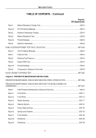
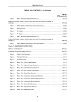
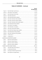
Figure 15.
Power Plant Water Cooler Removal.
..................................................................................
0211-28
Figure 16.
Power Plant Air Lines Assembly.
.......................................................................................
0211-29
Figure 17.
Power Plant Heater Shutoff Valves.
...................................................................................
0211-30
Figure 18.
Power Plant Lifting Points.
.................................................................................................
0211-31
Figure 19.
Power Plant Engine Mounts Installation.
............................................................................
0211-33
Figure 20.
Power Plant Transmission Wires Installation.
....................................................................
0211-35
Figure 21.
Power Plant Transmission Module Installation.
..................................................................
0211-37
Figure 22.
Power Plant Transmission Shifter Cable Installation.
.........................................................
0211-39
Figure 23.
Power Plant Electrical Wire Installation.
.............................................................................
0211-41
Figure 24.
Power Plant Air Line Installation.
........................................................................................
0211-43
Figure 25.
Power Plant Ether Line Installation.
...................................................................................
0211-45
Figure 26.
Power Plant Throttle Cable Installation.
.............................................................................
0211-47
Figure 27.
Power Plant Power Steering Hoses Installation.
................................................................
0211-49
Figure 28.
Power Plant Alternator Wiring Installation.
.........................................................................
0211-51
Figure 29.
Power Plant Temperature Wiring Installation.
....................................................................
0211-52
Figure 30.
In-Chassis Run-In.
..............................................................................................................
0211-53
Figure 31.
In-Chassis Run-In.
..............................................................................................................
0211-54
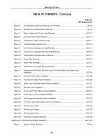
ENGINE AND CONTAINER REPLACEMENT.
...........................................................................................
WP 0212
Figure 1.
Engine and Container Removal.
..........................................................................................
0212-2
Figure 2.
Engine and Container Removal.
..........................................................................................
0212-3
Figure 3.
Engine and Container Installation.
.......................................................................................
0212-5
Figure 4.
Engine and Container Installation.
.......................................................................................
0212-7
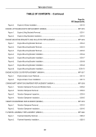
POWER PLANT REPLACEMENT (M939A2).
.............................................................................................
WP 0213
Figure 1.
Tachometer Cable and Drive Removal.
...............................................................................
0213-2
Figure 2.
Air Intake System Removal.
.................................................................................................
0213-3
Figure 3.
Fuel Supply and Electrical System Removal.
.......................................................................
0213-5
Figure 4.
Power System and Linkage Removal.
.................................................................................
0213-7
TM 9-2320-272-23-2
xii
Back to Top


