TM-9-2320-272-23-4 - Page 1373 of 1393
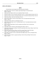
INSTALLATION (M939/A1)
NOTE
All male threads must be wrapped with antiseize tape before installation.
1.
Install bracket (Figure 4, Item 22) on radiator support bracket (Figure 4, Item 23) with screw
(Figure
4,
Item
29).
2.
Install shutoff valve (Figure 4, Item 10) on air compressor (Figure 4, Item 19).
3.
Install elbow (Figure 4, Item 12) and drain valve (Figure 4, Item 11) on alcohol evaporator (Figure 4, Item 13).
4.
Install air line (Figure 4, Item 9) on shutoff valve (Figure 4, Item 10) and alcohol evaporator (Figure 4, Item 13).
5.
Install bushing (Figure 4, Item 16) on tee (Figure 4, Item 14).
6.
Install vent hose (Figure 4, Item 8) on bushing (Figure 4, Item 15) and pressurized valve connector
(Figure
4,
Item
30).
7.
Install bushing (Figure 4, Item 17) on tee (Figure 4, Item 16).
8.
Install pressure hose (Figure 4, Item 7) on bushing (Figure 4, Item 17) and pressurized valve connector
(Figure
4,
Item
31).
9.
Install five tiedown straps (Figure 4, Item 18) on pressure hose (Figure 4, Item 7) and vent hose
(Figure
4,
Item
8).
10.
Install adapter (Figure 4, Item 20) on power steering pump (Figure 4, Item 21).
11.
Install power steering pump hose (Figure 4, Item 28) on pressurized valve connector (Figure 4, Item 27) and
adapter (Figure 4, Item 20).
12.
Install power steering pump hose (Figure 4, Item 28) on bracket (Figure 4, Item 22) with clamp
(Figure
4,
Item
25), screw (Figure 4, Item 24), and locknut (Figure 4, Item 26).
13.
Install supply hose (Figure 4, Item 4) on pressurized valve adapter (Figure 4, Item 1) and regulator valve
(Figure
4,
Item
6).
14.
Install clamp (Figure 4, Item 3) on supply hose (Figure 4, Item 4) with screw (Figure 4, Item 2) and nut
(Figure
4,
Item
5).
TM 9-2320-272-23-4
0770
0770-8
Back to Top


