TM-9-2320-272-23-4 - Page 255 of 1393
INSTALLATION
1.
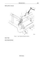
Insert bar end of tailgate latch (Figure 2, Item 8) through hole (Figure 2, Item 7) in dump body
(Figure
2,
Item
1) and install with three screws (Figure 2, Item 9), washers (Figure 2, Item 6), and locknuts
(Figure 2, Item 5).
2.
Insert yoke end of control rod (Figure 2, Item 13) to tailgate latch (Figure 2, Item 8).
3.
Insert link (Figure 2, Item 4) through hole in tailgate latch (Figure 2, Item 8) and yoke side of control rod
(Figure
2, Item 13).
4.
Insert link (Figure 2, Item 4) into hole in dump body (Figure 2, Item 1).
5.
Install link plate (Figure 2, Item 12) on link (Figure 2, Item 4) with two nuts (Figure 2, Item 11) and cotter pins
(Figure 2, Item 10).
6.
Install three crossshaft bearings (Figure 2, Item 3) on control rod (Figure 2, Item 13).
7.
Position three crossshaft bearings (Figure 2, Item 3) against outer bearing brackets (Figure 2, Item 23) and
install with six screws (Figure 2, Item 24) and locknuts (Figure 2, Item 22).
8.
Place tailgate control lever (Figure 2, Item 2) in OPEN position.
9.
Place woodruff key (Figure 2, Item 15) on tailgate control lever (Figure 2, Item 2).
10.
Install tailgate control lever (Figure 2, Item 2) on control rod (Figure 2, Item 13) with screw (Figure 2, Item 14)
and locknut (Figure 2, Item 16).
11.
Place clevis (Figure 2, Item 17) on threaded end of control rod (Figure 2, Item 13) and install washer
(Figure
2, Item 19) and clevis on tailgate control lever (Figure 2, Item 2) with screw (Figure
2, Item 21) and
locknut (Figure 2, Item 20).
NOTE
Repeat Steps (8) through (12) for tailgate control linkage at opposite side.
12.
Install adjusting nut (Figure 2, Item 18) on threaded end of control rod (Figure 2, Item 13).
TM 9-2320-272-23-4
0591
0591-4
Back to Top


