TM-9-2320-272-23-4 - Page 583 of 1393
ASSEMBLY
NOTE
•
Insulate areas of dissimilar metal-to-metal contact with zinc chromate primer.
•
Apply sealing compound to exterior joints prior to installation.
•
Insulate all enclosed structure with fibrous glass felt insulation.
•
Assistant will help with Step (1).
1.
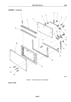
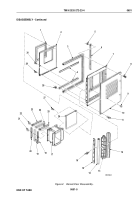
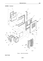
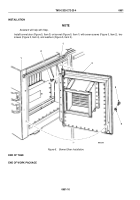
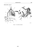
Install inner panel (Figure 4, Item 2) on frame (Figure 4, Item 7) with 33 rivets (Figure 4, Item 29) and two rivets
(Figure 4, Item 30).
2.
Install seal (Figure 4, Item 3) and retainer (Figure 4, Item 6) on frame (Figure 4, Item 7) with seven screws
(Figure 4, Item 8) and nuts (Figure 4, Item 5).
3.
Install two channel seals (Figure 4, Item 24), channels (Figure 4, Item 23), and channels (Figure 4, Item 25)
on intake assembly (Figure 4, Item 17) with ten rivets (Figure 4, Item 22).
4.
Install two channel seals (Figure 4, Item 19), channels (Figure 4, Item 18), and channels (Figure 4, Item 20)
on intake assembly (Figure 4, Item 17) with 14 rivets (Figure 4, Item 21).
NOTE
Assistant will help with Steps (6) and (7).
5.
Install preformed cork (Figure 4, Item 1), intake panel (Figure 4, Item 26) (if present), and intake assembly
(Figure 4, Item 17) on inner panel (Figure 4, Item 2) with 24 rivets (Figure 4, Item 27).
6.
Install outer panel (Figure 4, Item 10) on frame (Figure 4, Item 7) with 17 rivets (Figure 4, Item 9).
7.
Install two retainers (Figure 4, Item 4) in seal (Figure 4, Item 3) with 18 screws (Figure 4, Item 11) and nuts
(Figure 4, Item 28).
8.
Install seal (Figure 4, Item 12), hinge (Figure 4, Item 13), spacer plate (Figure 4, Item 15), and seal
(Figure
4,
Item
14) on frame (Figure 4, Item 7) with six screws (Figure 4, Item 16). Ensure hinge is flush with
top of door.
TM 9-2320-272-23-4
0651
0651-8
Back to Top

