TM-9-2320-272-23-5 - Page 24 of 623
TABLE OF CONTENTS
- Continued
Page No.
WP Sequence No.
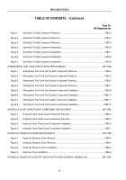
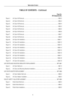
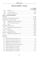
Figure 4.
Relief Valve Installation.
.......................................................................................................
0809-7
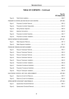
PNEUMATIC CONTROLLER AND RELIEF VALVE REPAIR.
....................................................................
WP 0810
Figure 1.
Pneumatic Controller Removal.
............................................................................................
0810-2
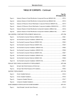
Figure 2.
Pneumatic Controller Disassembly.
.....................................................................................
0810-3
Figure 3.
Wiring Harness Inspection.
..................................................................................................
0810-5
Table 1.
Electrical Connections.
.........................................................................................................
0810-5
Figure 4.
Pneumatic Controller Assembly.
..........................................................................................
0810-7
Figure 5.
Pneumatic Controller Installation.
.........................................................................................
0810-8
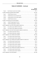
WATER SEPARATOR REPLACEMENT.
....................................................................................................
WP 0811
Figure 1.
Water Separator Removal.
...................................................................................................
0811-3
Figure 2.
Water Separator Installation.
................................................................................................
0811-5
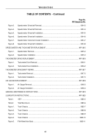
PRESSURE TRANSDUCER REPLACEMENT.
..........................................................................................
WP 0812
Figure 1.
Pressure Transducer Removal.
............................................................................................
0812-1
Figure 2.
Pressure Transducer Removal.
............................................................................................
0812-2
Figure 3.
Pressure Transducer Removal.
............................................................................................
0812-3
Figure 4.
Pressure Transducer Removal.
............................................................................................
0812-4
Figure 5.
Pressure Transducer Installation.
.........................................................................................
0812-5
Figure 6.
Pneumatic Controller Installation.
.........................................................................................
0812-6
Figure 7.
Pneumatic Transducer Installation.
......................................................................................
0812-7
Figure 8.
Pneumatic Transducer Installation.
......................................................................................
0812-8
Figure 9.
Pressure Transducer Installation.
.........................................................................................
0812-9
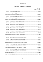
ELECTRONIC CONTROL UNIT (ECU) REPLACEMENT.
..........................................................................
WP 0813
Figure 1.
Electronic Control Unit Removal.
.........................................................................................
0813-1
Figure 2.
Electronic Control Unit Installation.
......................................................................................
0813-2
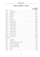
SPEEDOMETER DRIVESHAFT MAINTENANCE.
.....................................................................................
WP 0814
Figure 1.
Speedometer Driveshaft Removal.
......................................................................................
0814-1
Figure 2.
Speedometer Driveshaft Removal.
......................................................................................
0814-2
TM 9-2320-272-23-5
xi
Back to Top

