TM-9-2320-272-24-1 - Page 227 of 1015
TM 9-2320-272-24-1
Table 2-3. Electrical Troubleshooting (Contd).
MALFUNCTION
TEST OR INSPECTION
CORRECTIVE ACTION
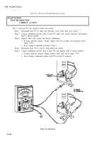
Test 2. Test flasher harness continuity.
Step 1.
Set multimeter to RX1 for continuity reading, and connect positive lead to terminal A of
flasher unit. Connect negative lead to terminal H of control unit cable, and observe
multimeter for continuity.
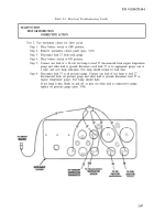
Step 2.
Connect multimeter negative lead to terminal F of control unit socket and positive lead
to terminal B of flasher unit. Observe multimeter for continuity.
Step 3.
Connect multimeter positive lead to terminal C of flasher unit connector. Connect
negative lead to ground, and observe multimeter for continuity.
a.
If any lead does not have continuity, repair (para. 3-131).
b.
If all leads have continuity and turn signals still do not work, replace flasher
(para. 3- 114).
c.
If turn signals still do not work, perform malfunction 25.
END OF TESTING!
2-139
Back to Top


