TM-9-2320-272-24-1 - Page 376 of 1015
3-4. ENGINE
EQUIPMENT CONDITION
Parking brake set (TM 9-2320-272-10).
Hood raised and secured (TM 9-2320-272-10).
Right splash shield removed (TM 9-2320-272-10).
Coolant drained (para. 3-53).
Engine oil drained and filter removed (para. 3-5).
Alternator removed (para. 3-80).
TM 9-2320-272-24-1
THIS TASK COVERS:
a. Removal
b. Disassembly
c. Cleaning and Inspection
d. Assembly
e. Installation
INITIAL SETUP:
APPLICABLE MODELS
M939A2
TOOLS
General mechanic’s tool kit (Appendix E, Item 1)
Torque wrench (Appendix E, Item 144)
Soft-jawed vise
MATERIALS/PARTS
Bypass valve (Appendix D, Item 31)
Gasket (Appendix D, Item 215)
Gasket (Appendix D, Item 230)
O-ring (early model engines only)
(Appendix D, Item 476)
Washer (Appendix D, Item 716)
Antiseize tape (Appendix C, Item 72)
REFERENCES (TM)
TM 9-2320-272-10
TM 9-2320-272-24P
GENERAL SAFETY INSTRUCTIONS
Pressure regulator is under spring tension. Use care
when removing plug.
NOTE
References to early model engines refer to engines with a serial
number before 44487830 used in M939A2 series vehicles.
1.
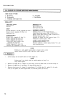
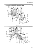
Loosen clamp (12) and remove hose (13) from nipple (11).
NOTE
Perform step 2 on vehicles with late model engines and step 3 on
early model engines.
2.
Remove oil supply line (1), adapter (2), and O-ring (3) from oil filter head (4). Discard O-ring (3).
3.
Remove oil supply line (1) and elbow (15) from oil filter head (4).
4.
Remove eleven screws (6), clamp (5), wiring harness (7), oil filter head (4), gasket (8), oil cooler
core (9), and gasket (10) from engine block (14). Discard gaskets (8) and (10).
3-12
Back to Top


