TM-9-2320-272-24-1 - Page 576 of 1015
TM
9-2320-272-24-1
THIS TASK COVERS:
a. Removal
c. Installation
b. Cleaning and Inspection
APPLICABLE
MODELS
M939A2
REFERENCES (TM)
TM
9-2320-272-10
TOOLS
TM 9-2320-272-24P
General mechanic’s tool kit (Appendix E, Item 1)
EQUIPMENT CONDITION
MATERIALS/PARTS
Parking brake set (TM 9-2320-272-10).
Hood raised and secured (TM 9-2320-272-10).
Cap and plug set (Appendix C, Item 14)
Coolant drained below water manifold level
Antiseize tape (Appendix C, Item 72)
(para. 3-53).
Fan and fan shroud removed (para. 3-64).
Drivebelt removed (para. 3-71).
1.
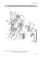
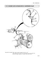
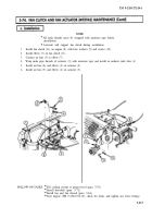
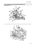
Disconnect air line (6) and elbow (2) from actuator (3).
2.
Disconnect air line (5) and elbow (4) from actuator (3).
NOTE
Note position of actuator for installation.
3.
Remove actuator (3) from radiator inlet tube (1).
4.
Disconnect air line (5) from elbow (7).
NOTE
Assistant will support fan clutch while removing screws.
5.
Remove four screws (10), washers (9), and fan clutch (11) from engine (8).
6.
Remove elbow (7) from fan clutch (11).
1.
Clean all parts (para. 2-14).
2.
Inspect air lines (5) and (6) for cracks, kinks, and wear.
3.
Inspect other parts (para. 2-15).
4.
Replace all parts failing inspection.
3-212
Back to Top

