TM-9-2320-272-24-1 - Page 594 of 1015
TM 9-2320-272-24-1
1.
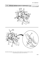
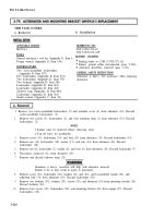
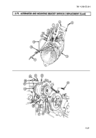
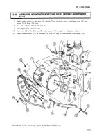
Install new woodruff key (8) and alternator pulley (9) on alternator (1).
2.
Place alternator pulley (9) in vise.
3.
Install washer (11) and new locknut (10) on alternator (1). Tighten locknut (10) 90-100 lb-ft
(122-136 N•m).
4.
Remove alternator pulley (9) from vise.
1.
2.
3.
4.
5.
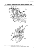
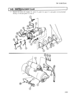
Install alternator link (14) on engine (5) with washer (13) and screw (12).
Install mounting bracket (6) on engine (5) with four screws (7).
Install alternator (1) on mounting bracket (6) and bracket (4) with two washers (3) and screws (2).
Finger-tighten screws (2).
Connect wire (28) to connector (29).
Install wire (25) on alternator (1) with new lockwasher (17) and nut (18). Tighten nut (18)
45-55 lb-in (5-6 N•m).
6.
Install wire (26) on alternator (1) with new lockwasher (19) and nut (20). Tighten nut (20) 20-25 lb-in
(2-3 N•m).
7.
Install wire (27) on alternator (1) with new lockwasher (21) and screw (22). Tighten screw (22)
82-102 lb-in (9-12 N•m).
8.
Pivot alternator (1) to align with alternator link (14).
9.
Install alternator link (14) on alternator (1) with washer (15) and screw (16).
10.
Install fan drivebelt (para. 3-71).
11.
Connect battery ground cables (para. 3-126).
12.
Adjust alternator (1) (task e.).
Alternator is heavy. Assistant will help with alternator
installation. Failure to do so may result in injury to personnel.
NOTE
Ensure wire connecting points are thoroughly cleaned before
connections are made.
1.
Start engine (TM 9-2320-272-10).
2.
Set engine speed to 1200 rpm (TM 9-2320-272-10)
3.
Turn on headlights (TM 9-2320-272-10) to place load on alternator (1).
4.
Using multimeter, check alternator (1) output voltage. Connect black lead to ground cable (27) and
touch red lead to wire (28). Output voltage should be 27.8-28.2 VDC. If adjustment is required,
continue with next step. If no adjustment is required, proceed to step 8.
5.
Using hex-head driver, remove pipe plug (30) from alternator (1).
6.
Turn adjusting screw counterclockwise to increase or clockwise to decrease voltage.
3-230
Back to Top

