TM-9-2320-272-24-1 - Page 688 of 1015
TM 9-2320-272-1
3-120. FLOODLIGHT CONTROL SWITCH MAINTENANCE
THIS TASK COVERS:
a. Removal
d. Assembly
b. Disassembly
e. Installation
c. Inspection
INITIAL SETUP:
APPLICABLE MODELS
REFERENCES (TM)
M936/A1/A2
TM 9-2320-272-10
TOOLS
TM 9-2320-272-24P
General mechanic’s tool kit (Appendix E, Item 1)
EQUIPMENT CONDITION
MATERIALS/PARTS
l
Parking brake set (TM 9-2320-272-10).
Two locknuts (Appendix D, Item 283)
l
Battery ground cables disconnected (para. 3-126).
Lockwasher (Appendix D, Item 355)
Lockwasher (Appendix D, Item 351)
a. Removal
1.
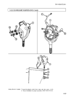
Remove two locknuts (1) and mounting screws (11) from angle bracket (2) and instrument panel (16).
Discard locknuts (1).
2.
Lower floodlight control switch (12).
NOTE
Tag connectors for installation.
3.
Disconnect four connectors (15) from floodlight control switch (12).
b. Disassembly
1.
Remove screw (7), lockwasher (6), switch lever (8), washer (5), and felt washer (9) from floodlight
control switch (12). Discard lockwasher (6).
2.
Remove nut (4), lockwasher (10), identification plate (3), angle bracket (21, plug (14), and shell (13)
from floodlight control switch (12). Discard lockwasher (10).
1.
Inspect floodlight control switch (12) for breaks and cracks in housing. Replace if housing is broken
or cracked.
2.
Inspect switch lever (8) for breaks and cracks. Replace if broken or cracked.
1.
Install shell (13), plug (14), angle bracket (2), and identification plate (3) on floodlight control
switch (12) with new lockwasher (10) and nut (4).
2.
Install felt washer (9), washer (5), and switch lever (8) on floodlight control switch (12) with new
lockwasher (6) and screw (7).
3-324
Back to Top


