TM-9-2320-272-24-1 - Page 728 of 1015
TM 9-2320-272-24-1
3-135. GOVERNOR PIPING
AND CAPACITOR MAINTENANCE
THIS TASK COVERS:
a. Removal
b. Inspection
c. Installation
INITIAL SETUP:
APPLICABLE MODELS
M936/A1/A2
REFERENCES (TM)
TM 9-2320-272-24-1
TOOLS
TM 9-2320-272-24P
a.
General
mechanic’s tool kit (Appendix E, Item 1)
EQUIPMENT CONDITION
MATERIALS/PARTS
Parking brake set (TM 9-2320-272-10).
Two locknuts (Appendix D, Item 313)
Lockwasher (Appendix D, Item 350)
Two cotter pins (Appendix D, Item 66)
Three tiedown straps (Appendix D, Item 684)
Antiseize tape (Appendix C, Item 72)
a. Removal
NOTE
l
Perform steps 1 and 2 for M936/A1 model vehicles only.
l
Have drainage container ready to catch oil.
1.
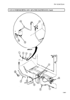
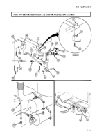
Remove hose (13) from elbow (14) and tee (2).
2.
Remove elbow (14) from governor (15).
3.
Remove cap (1) from tee (2).
4.
Remove hose (10) from tee (2).
5.
Remove tee (2) from nipple (3).
6.
Remove nipple (3) from adapter (4).
NOTE
Note location of tiedown strap for installation.
7.
Remove tiedown strap (12) from hoses (10) and (11). Discard tiedown strap (12).
8.
Remove hose (10) from adapter (9).
9.
Remove adapter (9) from tee (5).
10.
Remove hose (7) from elbows (8) and (6).
11.
Remove elbow (8) from tee (5).
3-364
Back to Top


