TM-9-2320-272-24-1 - Page 744 of 1015
TM 9-2320-272-24-1
3-141. TRANSMISSION OIL COOLER AND MOUNT (M939A2) REPLACEMENT
THIS TASK COVERS:
a. Removal
b. Installation
INITIAL SETUP:
APPLICABLE MODELS
M939A2
TOOLS
General mechanic's tool kit (Appendix E, Item 1)
MATERIALS/PARTS
Four locknuts (Appendix D, Item 291)
Four lockwashers (Appendix D, Item 354)
Two O-rings (Appendix D, Item 430)
Antiseize tape (Appendix C, Item 72)
Cap and plug ret (Appendix C, Item 14)
REFERENCES (TM)
TM 9-2320-272-10
TM 9-2320-272-24P
EQUIPMENT CONDITION
l
Parking brake ret (TM 9-2320-272-10).
l
Cooling system drained (para. 3-63).
a. Removal
1.
2.
3.
4.
5.
6.
CAUTION
l
Clean area around hoses before removal to prevent entry of dirt
Damage may occur if dirt or dust enters the transmission.
l
Cover or plug all open hoses and connections immediately after
disconnection to prevent contamination. Failure to do this may
result in transmission damage.
NOTE
Have drainage container ready to catch oil.
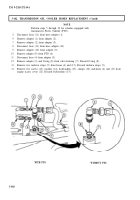
Disconnect transmission oil lines (4) and (18) from oil sampling valve (5) and elbow (15).
Loosen clamps (1) and (17) and disconnect hoses (2) and (16) from oil cooler (11).
Remove four locknuts (20), washers (10), screws (9), washers (10), and oil cooler (11) from
bracket (3) and splash panel extension (22). Discard locknuts (20).
Remove oil sampling valve (5), nut (6), washer (7), and O-ring (8) from oil cooler (11). Discard O-ring (8).
Remove elbow (16), nut (14), washer (13), and O-ring (12) from oil cooler (11). Discard O-ring (12).
Remove four locknuts (23), lockwashers (24), screws (21), and splash panel extension (22) from
bracket (25) and frame rail (19). Discard locknuts (23) and lockwashers (24).
3-380
Back to Top


