TM-9-2320-272-24-1 - Page 832 of 1015
TM 9-2320-272-24-1
3-170. UPPER AND LOWER TORQUE ROD MAINTENANCE
THIS TASK COVERS:
a. Upper Torque Rod Removal
b. Lower Torque Rod Removal
c. Cleaning and Inspection
d. Disassembly
INITIAL SETUP:
e. Assembly
f.
Setting Preload for Upper Torque Rod
g. Upper Torque Rod Installation
h. Lower Torque Rod Installation
APPLICABLE MODELS
All
TOOLS
General mechanic’s tool kit (Appendix E, Item 1)
Torque wrench (Appendix E, Item 145)
Arbor press
Vise
MATERIALS/PARTS
Four cotter pins (Appendix D. Item 47)
Four slotted nuts (Appendix D), Item 658)
Eight lockwashers (Appendix D, Item 362)
REFERENCES (TM)
TM 9-2320-272-10
TM 9-2320-272-24P
TM 9-237
EQUIPMENT CONDITION
Parking brake set (TM 9-2320-272-10).
Right rear spring assembly removed (for upper
torque rods only) (para. 3-167).
Two front-rear wheels removed (for lower torque
rods only) (para. 3-220 or 3-221).
GENERAL SAFETY INSTRUCTIONS
Eye shields must be worn when cleaning with a wire
brush.
1.
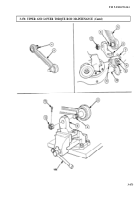
Remove four nuts (5), lockwashers (4), screws (3), and torque rod plate (6) from torque rod
bracket (1). Discard lockwashers (4).
2.
Remove cotter pin (8) from upper torque rod (2) and spring seat bracket (9). Discard cotter pin (8).
3.
Back off slotted nut (7) until even with ball shaft (10) and use slotted nut (7) as a striking surface.
4.
Drive torque rod ball shaft (10) out of spring seat bracket (9).
5.
Remove slotted nut (7) from ball shaft (10). Discard slotted nut (7).
6.
Remove upper torque rod (2) with upper torque rod bracket (1) from spring seat bracket (9).
7.
Place upper torque rod (2) and bracket (1) in vise.
8.
Remove cotter pin (11) and back off slotted nut (13) until even with end of ball shaft (12). Discard
cotter pin (11).
9.
Using nut (13) as striking surface, drive torque rod ball shaft (12) out of upper bracket (1).
10.
Remove slotted nut (13) from ball shaft (12). Discard slotted nut (13).
3-468
Back to Top


