TM-9-2320-272-24-1 - Page 872 of 1015
TM 9-2320-272-2-1
3-l83. FRONT BRAKE SPIDER REPLACEMENT
THIS TASK COVERS:
a. Removal
b. Installation
INITIAL SETUP:
APPLICABLE MODELS
REFERENCES (TM)
All
TM 9-2320-272-10
TOOLS
TM 9-2320-272-24P
General mechanic’s tool kit (Appendix E, Item 1)
EQUIPMENT CONDITON
Torque wrench (Appendix E, Item 144)
Brakeshoes removed (para. 3-180).
MATERIALS/PARTS
Service brake chamber removed (para. 3-181).
Two
lockwashers (Appendix D, Item 365)
Gasket sealant (Appendix C, Item 30)
1.
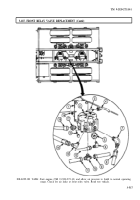
Remove nine nuts (6), washers (6), brake spider slinger (4), and brake spider (2) from studs (12).
2.
Remove two nuts (10), lockwashers (9), screws (7), and clips (8) from brake spider (2). Discard
lockwashers (9).
1.
Install two clips (8) on brake spider (2) with two screws (7), new lockwashers (9), and nuts (10).
2.
Apply gasket sealant to spindle (11) and brake spider (2) mating surfaces.
Failure to tighten nuts in proper sequence can crack brake spider.
Tighten front brake spider after installing front wheel dustcovers.
3.
Install brake spider (2) and brake spider slinger (4) on studs (12) with anchor plunger (3) at
1 o’clock position (left side) and anchor plunger (1) at 11 o’clock position (right side) with nine
washers (5) and nuts (6). Tighten nuts (6) 110-145 lb-ft (149-196 N•m) in sequence shown.
3-508
Back to Top


