TM-9-2320-272-24-1 - Page 886 of 1015
TM 9-2320-272-24-l
3-190. FRONT LIMITING VALVE REPLACEMENT
THIS TASK COVERS:
a. Removal
b. Installation
INITIAL SETUP:
APPLICABLE MODELS
All
TOOLS
General
mechanic’s tool kit (Appendix E, Item 1)
MATERIALS/PARTS
Two locknuts (Appendix D, Item 299)
Antiseize tape (Appendix C, Item 72)
REFERENCES (TM)
TM 9-2320-272-10
TM
9-2320-272-24P
EQUIPMENT CONDITION
Parking brake set (TM 9-2320-272-10).
Air reservoirs drained (TM 9-2320-272-10).
GENERAL SAFETY INSTRUCTIONS
Do not disconnect air lines before draining air
reservoirs.
Do not disconnect air lines before draining air reservoirs. Small
parts under pressure may shoot out with high velocity, causing
injury to personnel.
Tag air lines for installation.
Scribe fitting directions for installation.
1.
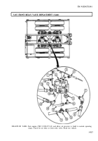
Disconnect two front service brake control lines (4) from tee (6).
2.
Disconnect doublecheck valve No. 1 control line (1) from adapter (2).
3.
Disconnect vent line (11) from elbow (6).
4.
Remove two locknuts (9), screws (7), and limiting valve (10) from mounting bracket (8). Discard
locknuts (9).
5.
Remove tee (5), elbow (6), and adapters (2) and (3) from limiting valve (10).
Wrap all male pipe threads with antiseize tape before installation.
1.
Install adapters (3) and (2), tee (5), and elbow (6) on limiting valve (10).
2.
Install limiting valve (10) on mounting bracket (8) with two screws (7) and new locknuts (9).
3.
Connect vent line (11) to elbow (6).
4.
Connect doublecheck valve No. 1 control line (1) to adapter (2).
5.
Connect two front service brake control lines (4) to tee (5).
3-522
Back to Top


