TM-9-2320-272-24-2 - Page 698 of 991
TM 9-2620-272-24-2
Table 4-1. Mechanical Troubleshooting (Contd).
MALFUNCTION
TEST OR INSPECTION
CORRECTIVE ACTION
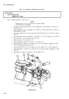
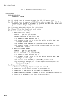
Step 2. Prepare hydraulic system for test.
a.
b.
C.
d.
e.
f.
g.
h.
i.
j.
k.
NOTE
l
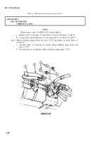
Perform steps a. and b. for M930/A1/A2 model vehicles.
l
Tag all hoses for installation.
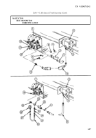
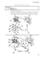
Disconnect front winch input hose (2) and output hose (1) from elbows (5) and (6) at
control valve (7).
Install appropriate caps (3) and plugs (4) on elbows (5) and (6) and hoses (1) and (2) to
block hydraulic oil flow.
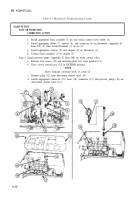
Disconnect supply hose (11) and return hose (10) from elbows (17) and (18) at control
valve (7).
Install appropriate caps (8) and plugs (9) on elbows (17) and (18) and hoses (10) and (11).
Disconnect line (14) from adapters (13) and (15).
Remove adapter (15) from elbow (16).
Install appropriate nipple (29) and tee (19) on elbow (16).
Install appropriate connector (23), reducer (24), nut (25), flowmeter (Appendix E, Item
169) (20), and connector (21) on tee (19).
Install appropriate hose (22) on connector (21) and adapter (13) at winch pump (12).
Install appropriate connector (27) and hose (26) on pressure gauge (Appendix E, Item
168) (28).
Install pressure gauge (28) with hose (26) on reducer (24).
M930/A1/A2
4-16
Back to Top


