TM-9-2320-272-24-2 - Page 711 of 991
TM 9-2320-272-24-2
Table 4-1. Mechanical Troubleshooting (Contd).
MALFUNCTION
TEST OR INSPECTION
CORRECTIVE ACTION
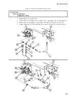
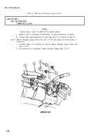
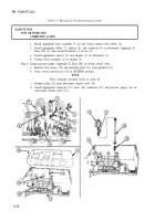
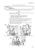
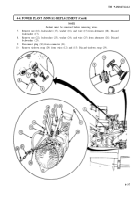
Step 18. Install pressure gauge (Appendix E, Item 168) on rear winch directional control valve.
NOTE
Ensure engine is off.
a.
b.
c.
d.
e.
Remove twelve screws (10), lockwashers (11), and control valve covers (12) and (13) from
wrecker (14). Discard lockwashers (11).
NOTE
If gauge port cover plate assembly or rear winch control valve is
equipped with pipe plug, proceed to step d. If gauge port cover
plate assembly is not equipped with pipe plug, proceed to step b.
Have drainage container ready to catch oil.
Remove four screws (15), lockwashers (16), cover plate assembly (19), and O-ring (17)
from rear winch control valve (18). Discard O-ring (17) and lockwashers (16).
Install new O-ring (17) and cover plate assembly (19) with plug (23) on rear winch
control valve (18) with four new lockwashers (16) and screws (15).
Remove plug (23) from cover plate assembly (19).
Install appropriate connector (24), hose assembly (20), connector (22), and pressure
gauge (21) on rear winch control valve (18).
4-29
Back to Top

