TM-9-2320-272-24-3 - Page 10 of 799
TM 9-2320-272-24-3
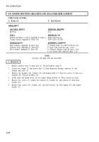
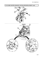
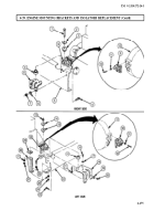
4-39. ENGINE MOUNTING BRACKETS AND ISOLATORS REPLACEMENT (Contd)
NOTE
Tag mounting brackets for installation.
Perform steps 7 through 9 for removing right engine mounting
brackets.
7.
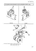
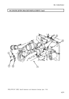
Remove two screws (1), washers (2), and four isolators (3) from upper mounting bracket (9) and
lower mounting bracket (8).
8.
Remove four locknuts (7), washers (6), screws (4), and lower mounting bracket (8) from frame
rail (5). Discard locknuts (7).
9.
Remove four screws (10), washers (11), and upper mounting bracket (9) from flywheel
housing (12).
NOTE
Perform steps 10 through 13 for removing left engine mounting
brackets.
10.
Remove two locknuts (13), washers (14), isolators (15), screws (21), and isolators (15) from upper
mounting bracket (30) and lower mounting bracket (18). Discard locknuts (13).
11.
Remove locknut (24), washer (25), screw (26), washer (25), locknut (27), washer (17), screw (16),
washer (17), shim (29), and engine support (28) from frame rail (22) and lower mounting bracket (18).
Discard locknuts (24) and (27).
12.
Remove four locknuts (20), washers (19), screws (23), and lower mounting bracket (18) from frame
rail (22). Discard locknuts (20).
13.
Remove four screws (32), washers (31), and upper mounting bracket (30) from flywheel housing (12).
b. Installation
1.
2.
3.
4.
5.
6.
7.
Perform steps 1 through 4 for installing left engine mounting
brackets.
Install upper mounting bracket (30) on flywheel housing (12) with four washers (31) and screws (32).
Tighten screws (32) 70-90-lb-ft (95-122 N·m).
Install lower mounting bracket (18) on frame rail (22) with four screws (23), washers (19), and new
locknuts (20). Tighten top two locknuts (20) 80-95 lb-ft (109-129 N·m). Tighten bottom two
locknuts (20) 55-70 lb-ft (75-95 N·m).
Install shim (29) and engine support (28) on frame rail (22) and lower mounting bracket (18) with
washer (17), screw (16), washer (17), new locknut (27), washer (25), screw (26), washer (25), and
new locknut (24). Tighten locknuts (24) and (27) 85 lb-ft (115 N·m).
Install four isolators (15) on upper (30) and lower (18) mounting brackets with two screws (21),
washers (14) and new locknuts (13). Finger-tighten screws (21).
NOTE
Perform steps 5 through 7 for installing right engine mounting
brackets.
Install upper mounting brackets (9) on flywheel housing (12) with four washers (11) and screws (10).
Tighten screws (10) 70-90 lb-ft (95-122 N·m).
Install lower mounting bracket (8) on frame rail (5) with four screws (4), washers (6), and new
locknuts (7).
Install four isolators (3) on upper mounting bracket (9) and lower mounting bracket (8) with two
washers (2) and screws (1). Finger-tighten screws (1).
NOTE
4-274
Back to Top

