TM-9-2320-272-24-4 - Page 154 of 836
TM 9-2320-272-24-4
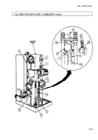
5-23. INJECTOR FLOW TEST
THIS TASK COVERS:
a. Setting Up Test Stand
b. Testing Check Ball Seating
c. Adjusting and Measuring Fuel Delivery
INlTIAL SETUP:
APPLICABLE MODELS
M939/Al
SPECIAL TOOLS
Injection tester (Appendix E, Item 49)
TOOLS
General mechanic’s tool kit (Appendix E, Item 1)
Burnishing tool adapter
Adjusting tool adapter
MATERIALS/PARTS
Gasket (Appendix D, Item 240)
Diesel fuel (Appendix C, Item 42)
REFERENCES (TM)
TM 9-2320-272-24P
EQUIPMENT CONDITION
• Fuel injector removed (para. 4-32).
•
Injector test stand calibrated (para. 5-22).
SPECIAL ENVIRONMENTAL CONDITIONS
Work area clean and free from blowing dirt and dust.
a. Setting Up Test Stand
1.
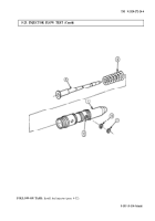
Remove screen retainer ring (5) and inlet fuel screen (4) from injector (3).
2.
Remove plunger (1) and spring (2) from injector (3) and separate plunger (1) from spring (2).
3.
Place plunger (1) in injector (3) without spring (2).
4.
Apply diesel fuel to lubricate inside of burnishing tool adapter.
CAUTION
Injector inlet port and burnishing tool adapter inlet hole must be
aligned to prevent damage to the burnishing tool points when
installed later.
5.
Position injector (3) in burnishing tool adapter so injector (3) inlet port and burnishing adapter inlet
holes align. Tighten locating screw (12) on burnishing tool adapter to install injector (3).
6.
Connect test stand inlet pressure line adapter (11) to burnishing tool adapter.
b. Testing Check Ball Seating
NOTE
Hold injector in hand; do not place in test stand holding device,
1.
Hold plunger (1) down in injector (3).
2.
Place motor switch (7) on injection tester in START position. Ensure temperature gauge (9) reads
90-95°F (32-35°C).
CAUTION
If temperature exceeds 135°F (57°C), drain and replace with new
test oil.
3.
Adjust regulator knob (9) by turning until pressure gauge (6) reads 150 psi (1,034 kPa).
4.
Check burnishing tool adapter installation hole (10) for leaks. A slight seepage is not harmful. If
leakage is found, replace check ball (para. 5-19).
5.
Place motor switch (7) in STOP position.
6.
Disconnect test stand inlet pressure line adapter (11) from burnishing tool adapter.
5-148
Back to Top


