TM-9-2320-272-24-4 - Page 180 of 836
TM 9-2320-272-24-4
5-27. CAMSHAFT AND GEAR MAINTENANCE
THIS TASK COVERS:
a. Check Backlash and End Play
b. Removal
c. Disassembly
d. Cleaning and Inspection
e. Assembly
f. Installation
INITIAL SETUP:
APPLICABLE MODELS
M939A2
SPECIAL TOOLS
Cam bushing replacement tool
(Appendix E, Item 26)
TOOLS
General mechanic’s tool kit (Appendix E, Item 1)
Gear puller (Appendix E, Item 102)
Dial indicator (Appendix E, Item 36)
Inside micrometer (Appendix E, Item 82)
Outside micrometer (Appendix E, Item 80)
Vernier caliper (Appendix E, Item 159)
Torque wrench (Appendix E, Item 144)
Arbor press
Prybar
MATERIALS/PARTS
Dowel pin (Appendix D, Item 98)
Lockwasher (Appendix D, Item 396)
GAA grease (Appendix C, Item 28)
Adhesive sealant (Appendix C, Item 4)
Rags (Appendix C, Item 58)
Drycleaning solvent (Appendix C, Item 71)
REFERENCES (TM)
TM 9-2320-272-24P
EQUIPMENT CONDITION
• Engine mounted on repair stand (para. 4-9).
• Rocker levers and push rods removed (para. 4-41).
• Flywheel housing removed (para. 4-43).
• Oil pan and suction tube removed (para. 4-47).
• Front gearcase cover removed (para. 4-48).
GENERAL SAFETY INSTRUCTIONS
• Keep fire extinguisher nearby when using
drycleaning solvent.
• Drycleaning solvent is flammable and toxic. Do
not use near open flame.
a. Check Backlash and End Play
1.
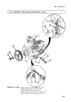
Rotate engine block (2) so bottom is facing upward.
2.
Install dial indicator on engine block (2) and crankshaft gear (1).
NOTE
Prevent crankshaft from rotating when checking backlash.
Reading will be the total of both gears.
3.
Rotate camshaft gear (3) clockwise until teeth contact teeth of crankshaft gear (1).
4.
Set dial indicator to zero.
5.
Rotate camshaft gear (3) counterclockwise until teeth contact crankshaft gear (1) teeth. Ensure
crankshaft gear (1) does not turn.
6.
Backlash of camshaft gear (3) should read 0.005-0.013 in. (0.13-0.33 mm). If reading is not within
limits, replace camshaft (tasks b through f.).
7.
Position dial indicator on face of camshaft gear (3). Press camshaft gear (3) towards rear of engine
block (1).
8.
Set dial indicator to zero.
9.
Pull camshaft gear (3) to front of engine block (1).
10.
End play of camshaft gear (3) should read 0.006-0.010 in. (0.152-0.254 mm). If reading is not within
limits, replace camshaft support (tasks b through f).
5-174
Back to Top


