TM-9-2320-272-24-4 - Page 316 of 836
TM 9-2320-272-24-4
5-46. TRANSMISSION OIL PUMP AND FRONT SUPPORT MAINTENANCE
THIS TASK COVERS:
a. Removal
d. Assembly
b. Disassembly
e. Installation
c. Cleaning and Inspection
INITIAL SETUP:
APPLICABLE MODELS
All
SPECIAL TOOLS
Two guide pins (Appendix E, Item 60)
Front support lifter (Appendix E, Item 48)
Bearing installer (Appendix E, Item 11)
Driver handle (Appendix E, Item 38)
Valve pin remover (Appendix E, Item 155)
Slide hammer (Appendix E, Item 122)
Main regulator and lockup spring compressor
(Appendix E, Item 129)
Adapters (Appendix E, Item 2)
Centering band (Appendix E, Item 90)
Bushing replacer (Appendix E, Item 25)
TOOLS
General mechanic’s tool kit (Appendix E, Item 1)
Depth micrometer (Appendix E, Item 81)
Torque wrench (Appendix E, Item 146)
Arbor press
MATERIALS/PARTS
Oil seal (Appendix D, Item 502)
Two self-locking screws (Appendix D, Item 649)
Twelve self-locking screws (Appendix D, Item 650)
Two hook-type seal rings (Appendix D, Item 638)
Twelve washers (Appendix D, Item 713)
Oil pump seal ring (Appendix D, Item 226)
Oil pump gasket (Appendix D, Item 227)
Valve guide pin (Appendix D, Item 705)
Lubricating oil (Appendix C, Item 47)
Oil-soluble grease (Appendix C, Item 53)
Sealing compound (Appendix C, Item 62)
REFERENCES (TM)
TM 9-2320-272-24P
EQUIPMENT CONDITION
Transmission manual selector shaft removed
(para. 5-45).
SPECIAL ENVIRONMENTAL CONDITIONS
Work area clean and free from blowing dirt and dust.
GENERAL SAFETY INSTRUCTIONS
Use care when removing snaprings and retaining
rings.
1.
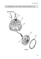
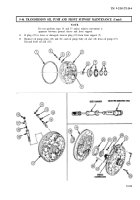
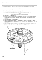
Position transmission (5) front upward.
2.
Remove twelve screws (2) and washers (1) connecting oil pump and front support (4) to
transmission (5). Discard washers (1).
3.
Attach front support lifter to converter ground sleeve (3) on oil pump and front support (4).
NOTE
Assistant will help with step 4.
4.
Remove oil pump and front support (4) from transmission (5) by lifting straight up. Assistant may
tap surface with a rubber hammer to ease removal.
5.
Remove oil pump gasket (6). Discard oil pump gasket (6).
5-310
Back to Top

