TM-9-2320-272-24-4 - Page 392 of 836
TM 9-2320-272-24-4
5-60. TRANSMISSION OIL PRESSURE TESTING
THIS TASK COVERS:
a. Oil Cooler Pressure Test
b. Main Pressure and Governor
Pressure Test
c. Automatic Shift Speed Test
INITIAL SETUP:
APPLICABLE MODELS
All
REFERENCES (TM)
TM 9-2320-272-10
TM 9-2320-272-24P
SPECIAL TOOLS
Pressure gauge set (300 psi) (Appendix E,
Item 51)
TOOLS
EQUIPMENT CONDITION
Parking brake set (TM 9-2320-272-10).
Transmission oil at proper level (TM 9-2320-272-10).
Vehicle at curb weight (empty) (TM 9-2320-272-10).
General mechanic’s tool kit (Appendix E, Item 1)
Wheels blocked (chocked) (TM 9-2320-272-10).
Drill press
21/64 drill bit
SPECIAL ENVIRONMENTAL CONDITIONS
1/4-18 NPTF tap
Work area clean and free from blowing dirt and
Pipe plug
dust.
Two pipe plugs
MATERIALS/PARTS
O-ring (Appendix D, Item 430)
GENERAL SAFETY INSTRUCTIONS
Personnel must be clear from underside and front of
vehicle when engine is running.
Cap and plug set (Appendix C,
Item 14)
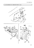
a. Oil Cooler Pressure Test
CAUTION
Before disconnecting transmission pressure lines, clean surrounding
surfaces and plug all openings to prevent entry of dirt or debris into
transmission. Damage will occur if dirt or debris enters transmission.
1.
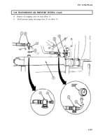
Disconnect oil cooler supply hose (1) from elbow (2) on top of oil cooler (7).
NOTE
Note elbow alignment for connection.
2.
Loosen nut (3) and remove elbow (2) and O-ring (4) from oil cooler (7). Discard O-ring (4).
3.
Using drill press and 21/64 drill bit, drill hole in side of elbow (2) opposite hose port.
4.
Tap hole in elbow (2) with 1/4-18 NPTF tap.
CAUTION
After tapping, elbow must be thoroughly cleaned and all burrs
and shavings removed. Any shavings entering system will damage
transmission.
5.
Remove elbow (2) from drill press and thoroughly clean.
6.
Install new O-ring (4) and elbow (2) in oil cooler (7) until aligned as noted in step 2.
7.
Tighten nut (3) until O-ring (4) is seated.
8.
Install pipe plug (8) on elbow (2).
9.
Connect oil cooler supply hose (1) to elbow (2).
5-386
Back to Top


