TM-9-2320-272-24-4 - Page 418 of 836
TM 9-2320-272-24-4
1.
2.
3.
4.
5.
6.
7.
8.
9.
10.
11.
12.
13.
14.
NOTE
Prior to assembly, apply coat of oil to lubricate all gears, bearings,
and shafts.
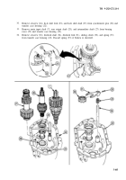
Measure thickness of bearing spacer (3). Replace bearing spacer (3) if thickness is less than
0.265 in. (6.73 mm).
Install low-speed gear spacer (5), low-speed gear (4), and bearing spacer (3) on main input shaft (6).
Ensure low-speed gear spacer (5) is aligned on dowel pin (8).
Using arbor press, install main input shaft bearing (2) on main input shaft (6).
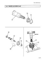
Measure thickness of bearing spacer (10). Replace bearing spacer (10) if thickness is less than
0.143 in. (3.63 mm).
Install synchronizer gear (13), high-speed gear spacer (12), high-speed gear (11), and bearing
spacer (10) on main input shaft (6). Ensure gear spacer (12) is aligned with dowel pin (7).
Using arbor press, install main input shaft bearing (9) on main input shaft (6).
Install companion flange spacer (1) on main input shaft (6).
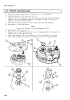
Using arbor press, install intermediate low-speed gear (15) and intermediate hearing (14) on
intermediate shaft (16).
Install intermediate high-speed gear (18) and roller bearing (21) on intermediate shaft (16).
Install new woodruff key (17) and speedometer gear (20) on intermediate shaft (16) with new
snapring (19).
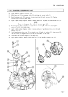
Using arbor press, install rear output shaft driven gear (24) and rear output shaft bearings (25)
and (22) on rear output shaft (23).
Install rear output shaft spacer (26) on rear output shaft (23).
Using arbor press, install front output shaft bearing (28) on front output shaft (27).
Install snapring (29) on front output shaft bearing (27).
5-412
Back to Top


