TM-9-2320-272-24-4 - Page 474 of 836
TM
9-2320-272-24-4
THIS TASK COVERS:
a. Removal
b. Installation
APPLICABLE MODELS
M9341/A1/A2
TOOLS
General mechanic’s tool kit (Appendix E, Item 1)
MATERIALS/PARTS
Two locknuts (Appendix D, Item 274)
Seal (Appendix D, Item 614)
Seal (Appendix D, Item 615)
Seal (Appendix D, Item 616)
REFERENCES (TM)
TM 9-237
TM 9-2320-272-10
TM 9-2320-272-24P
EQUIPMENT CONDITION
Parking brake set (TM 9-2320-272-10).
Van body sides fully expanded and secured
(TM 9-2320-272- 10).
Retractable beam rollers removed (para. 5-69).
Retractable beam drive shaft and lock removed
(para. 5-68).
SPECIAL ENVIRONMENTAL CONDlTlONS
Vehicle must be on level surface.
NOTE
All ten retractable beams are replaced the same way. This
procedure is for the left-rear retractable beam.
1.
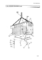
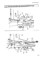
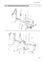
Break welds between side panel (1) and side panel support (13) and remove retractable beam (12)
(TM 9-237).
CAUTION
Remove retractable beam slowly from underframe. Failure to do so
may result in damage to equipment.
2.
Slide retractable beam (12) under side panel (1) and remove from underframe (4) and channel (5).
3.
Remove two locknuts (7), washers (8), screws (11), seven screws (10), retainer (9), and seals (2), (3),
and (6) from underframe (4). Discard locknuts (7) and seals (2), (3), and (6).
1.
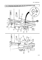
Install new seals (6), (3), and (2), and retainer (9) on underframe (4) with seven screws (10), two
screws (11), washers (8), and new locknuts (7).
CAUTION
Install retractable beam slowly into underframe. Failure to do so
may result in damage to equipment .
2.
Slide retractable beam (12) under side panel (1) and install in under-frame (4) at channel (5).
3.
Install retractable beam (12) by welding retractable beam (12) to side panel (1) and side panel
support (13) (TM 9-237).
5-468
Back to Top


