TM-9-2320-272-24P-1 - Page 33 of 1485
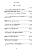
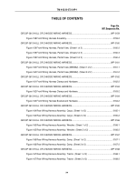
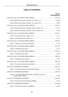
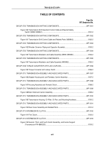
TABLE OF CONTENTS
Page No.
WP Sequence No.
Figure 271 Air Tank Reservoirs, Drainvalves, and Relate Lines.
................................................
0272-2
GROUP 1208 AIR BRAKE SYSTEM.
.................................................................................................
WP 0273
Figure 272 Spring Brake Reservoir, Mounting Hardware, Spring Brake Release
Valve, and Related Air Supply Lines.
.................................................................................
0273-2
GROUP 1208 AIR BRAKE SYSTEM.
.................................................................................................
WP 0274
Figure 273 Air Supply Lines, Double-Check Valve to Coupling to Push-Pull
Valve, and Supply Line Quick Release Valve to Tee to Fail-Safe Tee.
.............................
0274-2
GROUP 1208 AIR BRAKE SYSTEM.
.................................................................................................
WP 0275
Figure 274 Fail-Safe Air Brake Chamber Lines.
..........................................................................
0275-2
GROUP 1208 AIR BRAKE SYSTEM.
.................................................................................................
WP 0276
Figure 275 Air Supply Lines, Treadle Valve to Primary and Secondary Air Tanks,
and Relay Valves.
..............................................................................................................
0276-2
GROUP 1208 AIR BRAKE SYSTEM.
.................................................................................................
WP 0277
Figure 276 Dash Control Air Supply Lines, Spring Brake Control Valve to Primary
and Secondary Air Reservoirs.
..........................................................................................
0277-2
GROUP 1208 AIR BRAKE SYSTEM.
.................................................................................................
WP 0278
Figure 277 Treadle Valve to Quick Release Valve and Air Intake Tubing.
..................................
0278-2
GROUP 1208 AIR BRAKE SYSTEM.
.................................................................................................
WP 0279
Figure 278 Front Brake Chamber Vent Lines and Limiting Valve.
...............................................
0279-2
GROUP 1208 AIR BRAKE SYSTEM.
.................................................................................................
WP 0280
Figure 279 Vent Lines, Air Intake Manifold to Primary and Secondary Relay
Valves, and Rear Axle Vent Lines.
....................................................................................
0280-2
GROUP 1208 AIR BRAKE SYSTEM.
.................................................................................................
WP 0281
Figure 280 Secondary Vent Lines, Rear Axle Brake Chambers to Fail-Safe Brake
Chamber.
...........................................................................................................................
0281-2
GROUP 1208 AIR BRAKE SYSTEM.
.................................................................................................
WP 0282
Figure 281 Primary Vent Lines, Rear Axle Air Brake.
..................................................................
0282-2
GROUP 1208 AIR BRAKE SYSTEM.
.................................................................................................
WP 0283
Figure 282 Alcohol Evaporator and Air Compressor to Air Governor Lines.
...............................
0283-2
GROUP 1208 AIR BRAKE SYSTEM.
.................................................................................................
WP 0284
TM 9-2320-272-24P-1
xxiv
Back to Top

