TM-9-2320-273-10 - Page 19 of 452
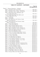
TABLE OF CONTENTS - CONTINUED
Page No.
WP Sequence No.
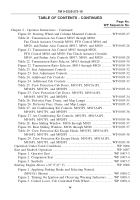
Chapter 2 - Operator Instructions - Continued
Figure 4. Disengaging PTO, (M916 through M920 Models) .
...............
WP 0008-5
Figure 5. Differential Control Switch and Engine Start Button .
............
WP 0008-6
Figure 6. Engine Retarder Foot Switch and Accelerator Pedal .
............
WP 0008-7
Figure 7. Engine Start Button .
.................................................................
WP 0008-7
Figure 8. Instrument and Indicator Panel Gauges and Indicators .
.........
WP 0008-9
Cold Weather Starting Below +32° F (0° C) .
................................................
WP 0009
Figure 1. Applying Parking Brake and Selecting Neutral .
.....................
WP 0009-2
Figure 2. Turning Engine Run Switch On and
Observing Warning Indicators .
.........................................................
WP 0009-3
Figure 3. Control Lever, Cab Controlled Fifth Wheel .
..........................
WP 0009-3
Figure 4. Disengaging PTO, (M916 through M920 Models) .
...............
WP 0009-4
Figure 5. Differential Control Switch and Engine Start Button .
............
WP 0009-5
Figure 6. Engine Retarder Foot Switch and Accelerator Pedal .
............
WP 0009-6
Figure 7. Starting Engine .
........................................................................
WP 0009-7
Figure 8. Instrument and Indicator Panel Gauges and Indicators .
.........
WP 0009-9
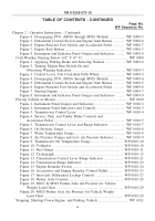
Placing Vehicle in Motion .
..............................................................................
WP 0010
Figure 1. Instrument Panel Gauges and Indicators .
................................
WP 0010-3
Figure 2. Instrument Panel Indicators and Controls .
..............................
WP 0010-3
Figure 3. Transmission Control Lever .
...................................................
WP 0010-4
Figure 4. Service, Park, and Trailer Brake Controls and
Accelerator Pedal .
.............................................................................
WP 0010-5
Figure 5. Transmission Control Lever and Range Indicator .
.................
WP 0010-7
Figure 6. Oil Pressure Gauge .
.................................................................
WP 0010-8
Figure 7. Water Temperature Gauge .
......................................................
WP 0010-9
Figure 8. Air Pressure Gauges and Low Air Pressure Indicator .
..........
WP 0010-9
Figure 9. Transmission Oil Temperature Gauge .
..................................
WP 0010-10
Figure 10. Voltmeter .
.............................................................................
WP 0010-10
Figure 11. Fuel Gauge .
..........................................................................
WP 0010-11
Figure 12. Tachograph .
..........................................................................
WP 0010-15
Figure 13. Transmission Control Lever Range Indicator .
....................
WP 0010-21
Figure 14. Transmission Range Indicator .
............................................
WP 0010-23
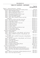
Figure 15. Engine Retarder Switch .
......................................................
WP 0010-24
Figure 16. Accelerator and Engine Retarder Control Pedals .
..............
WP 0010-25
Figure 17. Inter-axle Differential Lockup Controls .
.............................
WP 0010-27
Figure 18. Pusher Axle Controls .
..........................................................
WP 0010-28
Figure 19. M917 & M919 Pusher Axle Air Pressure for Vehicle
Weight Load Chart .
........................................................................
WP 0010-29
Figure 20. M920 Pusher Axle Air Pressure for Vehicle Weight
Load Chart .
.....................................................................................
WP 0010-29
Stopping, Shutting Down Engine, and Parking Vehicle .
...............................
WP 0011
TM 9-2320-273-10
v
Back to Top

