TM-9-2320-273-10 - Page 202 of 452
M915A1 FIFTH WHEEL OPERATION
WARNING
To avoid unintentional fifth wheel movement during tractor
operation, always ensure fifth wheel control is in the LOCK
position before placing tractor in normal operation. Failure to
comply may result in damage to equipment and serious
injury or death to personnel. Seek medical attention in the
event of an injury.
Never move fifth wheel control to the UNLOCK position
during normal tractor operation. Failure to comply may
result in loss of control, damage to equipment, and serious
injury or death to personnel. Seek medical attention in the
event of an injury.
All personnel must stand clear of tractor and trailer during
coupling operations. Failure to comply may result in injury
or death to personnel. Seek medical attention in the event of
an injury.
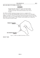
The M915A1 truck tractor is equipped with a cab controlled sliding fifth wheel for use
with trailers having a 2 in. (50.8 mm) diameter kingpin. The fifth wheel is
36 in. (91.4 cm) in diameter and can oscillate or pitch 15 degrees fore and aft. Rated
vertical load capacity is 40,000 lb (18,144 kg). Drawbar pull capacity is 150,000 lb
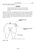
(68,039 kg). There are two kingpin lock releases on the left side of the fifth wheel, as
shown in figure 3. To uncouple trailer kingpin from the fifth wheel, first pull the
primary lock release handle, then pull the secondary lock release handle.
Moving fifth wheel control lever inside the cab to the UNLOCK position operates an
air cylinder under the fifth wheel which allows it to travel on the slide track a total of
12 in. (30.5 cm) forward or backward. This feature allows for adjustment of the
amount of cargo load carried by the rear tandem axles, within rated capacity.
With trailer coupled to the fifth wheel and the control in the UNLOCK position,
adjustment is made by driving forward or backward slowly with the trailer brake hand
control applied. After sliding adjustment is made, move fifth wheel control lever to the
LOCK position and release trailer brake hand control.
Use of the sliding fifth wheel for axle weight distribution requires scales to determine
weight placed on each axle of the tractor and trailer. The normal position of the sliding
fifth wheel is between the two rear tandem axles of the tractor with an unloaded or
loaded trailer. From this starting position, weight on the front axle of the tractor can be
increased by moving the sliding fifth wheel forward, and decreased by moving the
sliding fifth wheel backward. See normal location decals on both sides of the fifth
wheel assembly for correct positioning when towing the M872 trailer.
TM 9-2320-273-10
0012
0012-4
Back to Top


