TM-9-2320-273-20 - Page 1004 of 1500
TM 9-2320-273-20
BRAKE SYSTEM.
9-22. SERVICE BRAKES QUICK RELEASE VALVE (Continued).
LOCATION/lTEM
ACTION
REMARKS
A. REMOVAL .
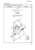
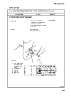
1. Three air lines (2).
2. Two bolts (6), washers (5),
and nuts (4).
3. Valve (3).
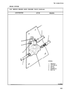
B. INSTALLATION.
4. Valve (3).
5. Valve
6. T
W O
3).
washers (5) and nuts (4).
7. Three air lines (2).
C. OPERATIONAL CHECK.
8. Engine.
9. CAB/Brake pedal.
10. Valve (3).
11. Engine.
a. Unscrew and remove.
b. Inspect for:
1. Leaks.
2. Cracks.
3. Damaged threads.
Unscrew and remove.
Remove from bracket (1).
Transfer all components
(elbows, adapters, etc.) to
new valve. Use liquid teflon
on threaded joints.
a. Coat threads with liquid
teflon.
b. Set onto bracket (7) and
install two bolts (6).
Install on bolts (6) and tighten.
Screw on and tighten.
Start up (see TM 9-2320-
273-10). Allow system to
reach operating pressure of
105-120 psi (724-827 kPa).
Press down and release.
a. Check that air exhausts
from valve when brake
pedal is released.
b. Use soap solution to check
for leaks.
Shut down (see
TM 9-2320-273-10).
Replace if necessary.
Second mechanic.
9-84
Back to Top


