TM-9-2320-279-20-1 - Page 687 of 985
TM 9-2320-279-20-1
Electrical System Maintenance Instructions (Cont)
7-42. HEATER FAN SWITCH REMOVAL/INSTALLATION.
This task covers:
a. Removal
c. Follow-on Maintenance
b. Installation
INITIAL SETUP
Models
References
All
None
Test Equipment
Equipment Condition
None
TM or Para
Condition Description
Special Tools
Para 7-91
Batteries disconnected.
None
Para 16-11
Heater compartment cover
Supplies
removed.
Tags, identification, Item 48, Appendix C
Special Environmental Conditions
Personnel Required
None
MOS 63S, Heavy wheel vehicle mechanic
General Safety Instructions
None
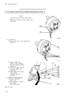
(1)
(2)
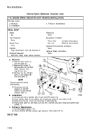
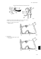
a. Removal.
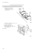
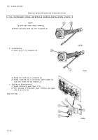
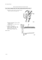
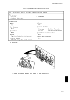
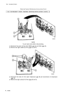
Remove four screws (1).
Remove jamnut (2) and
heater fan switch (3) from
back of heater control
panel (4).
NOTE
Tag and mark wires before
disconnecting.
(3)
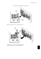
Disconnect wires (5) from
heater fan switch (3).
b. Installation.
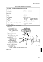
(1)
Connect wires (5) to heater
fan switch (3).
(2) Install heater fan switch (3)
and jamnut (2) in heater
control panel (4).
(3)
Install four screws (1).
c. Follow-on Maintenance.
(1) Connect batteries
(para 7-91).
(2)
Check operation of heater fan switch (TM 9-2320-279-10).
(3)
Install heater compartment cover (para 16-11).
END OF TASK
7-118
Back to Top

