TM-9-2320-279-20-2 - Page 650 of 938
TM 9-2320-279-20-2
Cab and Body Maintenance lnstructions (Cont)
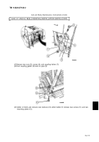
(6)
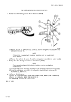
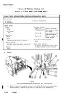
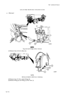
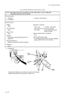
Soldier A holds and removes two locknuts (13) while Soldier B removes two screws (14) from
hose reel (15) and wheel well (16).
(7)
Soldier A and Soldier B remove hose reel (15).
b. Installation.
NOTE
Both fuel hose reels are installed the
same way. MC MANUAL CONTROL EM
VALVE
is on right
side only.
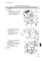
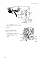
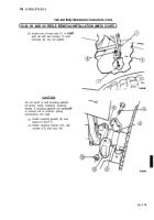
(1)
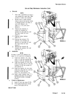
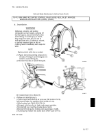
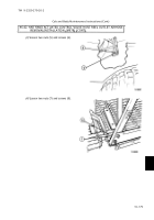
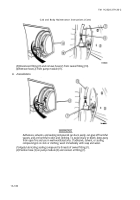
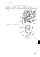
Soldier A and Soldier B position hose
reel (1) in pump module (2).
(2)
Install two mounting plates (3) with
screws (4) and locknuts (5). Do not
tighten.
16-172
Back to Top

