TM-9-2320-279-34-1 - Page 530 of 709
TM 9-2320-279-34-1
Transmission Maintenance Instructions (Cont)
7-20. CONTROL VALVE BODY REMOVAL/REPAlR/INSTALLATION (CONT).
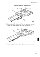
(31)
(32)
(33)
(34)
(35)
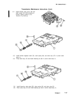
Install governor screen assembly (69)
and plug (70) in control valve body (1).
Tighten plug to 4 to 5 lb-ft (5 to 7 N•m).
Install accumulator valve (71),
spring (72), and valve stop (73) in
control valve body (1).
Aline pinhole in valve stop (73) with
pinholes in control valve body (1).
Press valve stop (73) and install
retaining pin (74) in control valve
body (1).
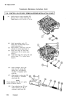
Install valve stop (75), spring (76), and
priority valve (77) in control valve
body (1).
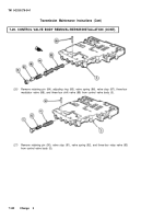
(36)
Install modulator valve (78),
valve stop (79), spring (80),
washer (81), and adjusting
ring (82) in modulator valve
body (83).
(37)
Aline pinhole in valve stop (79)
with pinholes in modulator
valve body (83).
NOTE
Ensure adjusting ring (82) is in same
position as before removal.
(38)
Press adjusting ring (82) and
install retaining pin (84) in
modulator valve body (83).
7-150
Change 3
Back to Top


