TM-9-2320-280-20-2 - Page 22 of 951
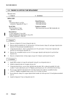
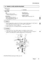
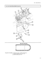
3-2. ENGINE OIL DIPSTICK TUBE REPLACEMENT
This task covers:
a. Removal
b. Installation
INITIAL SETUP:
Tools
General mechanic’s tool kit:
automotive (Appendix B, Item 1)
Special Tools
Hex-head driver, 8 mm
(Appendix B, Item 156)
Materials/Parts
O-ring (Appendix G, Item 209)
Plain-assembled nut (Appendix G, Item 201)
Sealant (Appendix C, Item 38)
Manual References
TM 9-2320-280-10
TM 9-2320-280-24P
Equipment Condition
Hood raised and secured (TM 9-2320-280-10).
1.
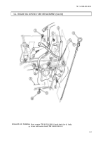
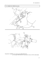
Remove oil dipstick (5) from oil dipstick tube (4).
2.
Remove plain-assembled nut (3) and capscrew (13) from harness clamp (2) and upper dipstick tube
bracket (6). Discard plain-assembled nut (3).
3.
Using hex-head driver, remove socket-head screw (8) and washer (7) from lower dipstick tube
bracket (12) and exhaust manifold (11).
4.
Remove two assembled-washer screws (1) from upper dipstick tube bracket (6) and fuel line
bracket (14).
5.
Remove oil dipstick tube (4) from engine oil pan (10). Remove and discard O-ring (9).
1.
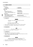
Apply RTV sealant to O-ring (9) and install O-ring (9) on oil dipstick tube (4).
2.
Install oil dipstick tube (4) in engine oil pan (10).
3.
Using hex-head driver, secure lower dipstick tube bracket (12) to exhaust manifold (11) with
washer (7) and socket-head screw (8). Tighten socket-head screw (8) to 25-33 lb-ft (34-45 N
•
m).
4.
Secure upper dipstick tube bracket (6) to fuel line bracket (14) with two assembled-washer
screws (1). Tighten assembled-washer screws (1) to 3–4 lb-ft (4-5 N
•
m).
5.
Secure harness clamp (2) to upper dipstick tube bracket (6) with capscrew (13) and plain-assembled
nut (3).
6.
Install oil dipstick (5) into oil dipstick tube (4).
b. Installation
a. Removal
TM 9-2320-280-20-2
3-2
Change 3
Back to Top


