TM-9-2320-280-20-2 - Page 739 of 951
7-14. HYDRO-BOOST REPLACEMENT
This task covers:
a. Removal
b. Installation
INITIAL SETUP:
Tools
General mechanic’s tool kit:
automotive (Appendix B, Item 1)
Materials/Parts
Cotter pin (Appendix G, Item 15)
Spring tension washer (Appendix G, Item 317)
Four lockwashers (Appendix G, Item 146)
(Basic/A1 Series)
Four lockwashers (Appendix G, Item 133)
(A2 Series)
Personnel Required
One mechanic
One assistant
Manual References
TM 9-2320-280-24P
Equipment Condition
Master cylinder removed (para. 7-13).
CAUTION
Cover or plug all open lines and connections immediately after
disconnection to prevent contamination. Remove all plugs prior to
connection.
NOTE
Have drainage container ready to catch brake fluid.
1.
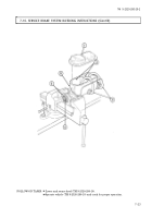
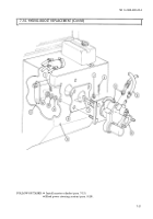
Mark and disconnect two high pressure lines (4) and one return line (5) from hydro-boost (6).
2.
Remove cotter pin (3), washer (2), and disconnect pushrod (7) from brake pedal bellcrank (13).
Remove spring tension washer (1) from brake pedal bellcrank (13) and discard cotter pin (3) and
spring tension washer (1).
3.
Remove four nuts (12), lockwashers (11), washers (10), hydro-boost (6), and gasket (8) from cowl (9).
Discard lockwashers (11).
1.
Install gasket (8) and hydro-boost (6) on cowl (9) with four washers (10), lockwashers (11), and
nuts (12).
2.
Install spring tension washer (1) on brake pedal bellcrank (13). Connect hydro-boost pushrod (7) to
brake pedal bellcrank (13). Install washer (2) and cotter pin (3).
3.
Tighten nuts (12) to 21 lb-ft (28 N
•
m).
4.
Connect two high pressure lines (4) and one return line (5) to hydro-boost (6).
b. Installation
a. Removal
TM 9-2320-280-20-2
7-30
Change 3
Back to Top


