TM-9-2320-280-20-3 - Page 185 of 1168
10-94. LEFT DEFROSTER NOZZLE REPLACEMENT
This task covers:
a. Removal
b.
Installation
INITIAL SETUP:
Tools
General mechanic’s tool kit:
automotive (Appendix B, Item 1)
Materials/Parts
Lockwasher (Appendix G, Item 183)
Locknut (Appendix G, Item 128)
Locknut (Appendix G, Item 126)
Adhesive sealant (Appendix C, Item 10)
Manual References
TM 9-2320-280-10
TM 9-2320-280-24P
Equipment Condition
• Hood raised and secured (TM 9-2320-280-10).
• Engine access cover removed (para. 10-15).
TM 9-2320-280-20-3
10-160
Change 2
1.
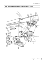
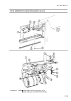
Remove eight capscrews (5) and retainer (6) from closeout panel (4) and “A” beam (7).
2.
Remove three nuts (20), washers (17), capscrews (16), and washers (17) from three clamps (18),
cable clamp (19), closeout panel (4), and “A” beam (7).
3.
Remove three screws (21) and closeout panel (4) from “A” beam (7).
4.
Loosen clamp (2.1) and disconnect defroster duct (3) from defroster nozzle (2).
5.
Remove locknut (9), lockwasher (10), washer (11), and pin (14) from steering column (15) and
bracket (13), and lower steering column (15). Discard locknut (9) and lockwasher (10).
NOTE
Perform steps 5.1 and 5.2 for M1097A2 and M1123 series vehicles only.
5.1.
Remove nut (15.1), screw (15.3), and ground wire 57C (15.2) from steering column (15).
5.2.
Remove locknut (15.5), washer (15.6), capscrew (15.8), washer (15.7), and two brackets (15.4) from
steering column (15). Discard locknut (15.5).
6.
Remove retaining pin (12) from defroster nozzle (2) and bracket (13).
NOTE
Note position of defroster nozzle for installation.
7.
Turn defroster nozzle (2) counterclockwise and remove from “A” beam (7).
1.
Install defroster nozzle (2) on “A” beam (7).
2.
Turn defroster nozzle (2) clockwise until defroster nozzle outlets (8) align with windshield frame
louvers (1).
3.
Install defroster nozzle (2) on bracket (13) with retaining pin (12).
NOTE
Perform steps 3.1 and 3.2 for M1097A2 and M1123 series vehicles only.
3.1.
Install two brackets (15.4) on steering column (15) with washer (15.7), capscrew (15.8),
washer (15.6), and locknut (15.5).
3.2.
Install ground wire 57C (15.2), screw (15.3), and nut (15.1)
on steering column (15).
4.
Place steering column (15) in desired position, and install on bracket (13) with pin (14),
washer (11), lockwasher (10), and locknut (9). Tighten locknut (9) to 31 lb-ft (42 N
•
m).
5.
Apply adhesive and connect defroster duct (3) to defroster nozzle (2) and tighten clamp (2.1).
b. Installation
a. Removal
Back to Top

