TM-9-2320-280-34 - Page 1105 of 1258
2 2 - 9 . 4 . RIGHT FRONT FLOOR PANEL REPAIR
TM 9-2320-280-34
2 2 -1 6 . 5 2
Change 1
This Task Covers:
a
. Right Front Insert Panel Fabrication
f
.
Metal Strip C and Insert Panel A s s e m b
l y
b
. Metal Strips Fabrication
g
.
Right Front FloorPanel and Battery Tray Drilling
c
.
Right Front FloorPanel Removal
h
. Right Front FloorPanel and Insert Panel Drilling
d
. Metal Strip Aand Insert Panel A s s e m b
l y
i
.
B a t t e ry Tray Panel and Right Front FloorPanel Installation
e
.
Metal Strip B and Insert Panel A s s e m b
l y
j
.
I n s e rt Panel and Right Front FloorPanel Installation
INITIAL SETUP:
Tools
General mechanic’s tool set:
automotive (Appendix G, Item 1)
Manual References
TM 9-2320-280-24P
TM 9-2320-280-20
TM 43-0139
Materials/Parts
Seventy-five rivets (Appendix E, Item 143)
Fifty-five rivets (Appendix E, Item 144)
Adhesive (Appendix B, Item 1.1)
Adhesive sealant (Appendix B, Item 4.1)
Front battery holdown bracket
(Appendix E, Item 1.1)
Rear battery holdown bracket
(Appendix E, Item 1.2)
Battery tray panel (Appendix E, Item 210.2)
Sheet metal (Appendix E, Item 200.1)
Equipment Condition
• Battery cover removed (TM 9-2320-280-20).
• Batteries removed (TM 9-2320-280-20).
• Battery tray removed (TM 9-2320-280-20).
• Right front floor insulation removed
(TM 9-2320-280-20).
Maintenance Level
General Support
NOTE
All dimensions in this procedure are in inches.
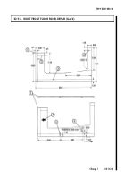
1.
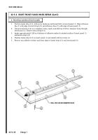
Cut insert panel (1) from sheet metal, and mark four reference lines (2) and directional arrow (3) on
insert panel (1).
2.
Fabricate two drain holes (4) in insert panel (1).
3.
Remove all burrs and round all sharp edges of insert panel (1).
a
. Right Front Insert Panel Fabrication
Back to Top

