TM-9-2320-280-34 - Page 650 of 1258
TM 9-2320-280-34
14-10.
AMBULANCE HEATER REPAIR (MODEL 10530A) (Cont ’d)
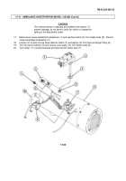
17.
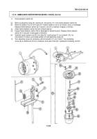
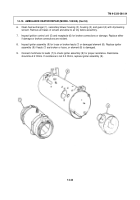
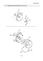
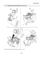
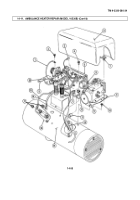
Route blower assembly lead (1) through hole in housing (4) and install with grommet (2) on housing (4).
18.
Align slots (5) in blower assembly (6) with four screw-assembled lockwashers (3) on housing (4),
engage blower assembly (6) on screw-assembled lockwashers (3), and turn clockwise to lock in blower
assembly slots (5).
Tighten four screw-assembled lockwashers (3).
19.
Install igniter cover ground strap (14), lockwasher (15), and receptacle ground lead (7) on ignition
control base stud (13) with nut and lockwasher assembly (8).
20.
Connect short igniter lead (12) to igniter cover terminal (11) and long igniter lead (10) to ignition control
unit terminal (9).
21.
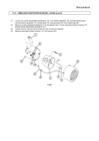
Install fuel control valve (17) on housing (4) with four screw-assembled lockwashers (18).
22.
Connect fuel tube (19) on fuel control valve inlet (16) with nut (20).
23.
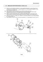
Route blower motor lead (1), and fuel control valve leads (22), (24), and (25) through clamp (26).
24.
Connect fuel control valve lead B (22) on receptacle (23) with screw-assembled lockwasher (21).
25.
Connect fuel control valve lead 30 (25) on overheat switch stud (34) with nut and lockwasher assembly
(33).
26.
Install ignition control lead wire 9 (31), lockwasher (30), receptacle lead wire 9 (29), lockwasher (28),
and fuel control valve thermostat lead wire 9 (24) on overheat switch stud (32) with nut and lockwasher
assembly (27).
27.
Connect blower motor lead (1) on flame detector switch (37) with screw-assembled lockwasher (36).
28.
Group fuel control valve leads (22), (24), and (25), and blower motor lead (1) together with two tiedown
straps (38).
29.
Install guard (35) on housing (4) with two dzus fasteners (39).
14-50
Back to Top

