TM-9-2320-280-34 - Page 82 of 1258
TM 9-2320-280-34
3-10.
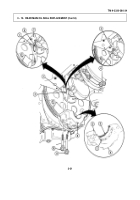
TIMING CHAIN COVER, TIMING CHAIN, AND DRIVE SPROCKETS MAINTENANCE (Cont ’d)
c.
Installation
1.
Install woodruff key (8) in camshaft (7) and two woodruff keys (9) in crankshaft (10).
2.
Install crankshaft sprocket (11) and camshaft sprocket (5) in timing chain (6) and align timing marks
(12).
3.
Rotate crankshaft (10) and camshaft (7) so woodruff keys (8) and (9) align with keyway slots in
crankshaft sprocket (11) and camshaft sprocket (5).
CAUTION
Timing marks on crankshaft sprocket and camshaft sprocket must remain aligned after
installation, or engine damage may result.
4.
Install crankshaft sprocket (11), camshaft sprocket (5), and timing chain (6) as an assembly onto
camshaft (7) and crankshaft (10).
5.
Install pump drive gear (3) on camshaft (7) with timing mark (4) at 0 °
with washer (2) and capscrew (1).
Tighten capscrew (1) to 55-66 lb-ft (75-90 Nm).
6.
Apply lubricating oil to timing chain (6).
NOTE
Perform step 7 only if timing chain was replaced.
7.
Using dial indicator, check timing chain deflection midway between camshaft sprocket (5) and
crankshaft sprocket (11).
Total deflection must not exceed 0.5 in.
(12.7 mm).
If deflection exceeds
specification, inspect camshaft sprocket (5) and crankshaft sprocket (11) for damage.
Replace either
if damaged and recheck deflection.
8.
Apply a 0.094 in.
(2.4 mm) bead of flange sealant to sealing surface on timing chain cover (18),
following diagram shown.
9.
Install gasket (21) and timing chain cover (18) on cylinder block (26) with four capscrews (30), washers
(29), and short capscrew (31).
Tighten four capscrews (30) and short capscrew (31) to 33 lb-ft (45
N m).
10.
Secure timing chain cover (18) to oil pan (28) with four capscrews (27).
Tighten capscrews (27) to 4-10
lb-ft (5-14 N m).
CAUTION
Maintain 0.040 in.
(1.02 mm) minimum clearance between baffle plate and pump drive
gear to avoid noise.
11.
Install baffle plate (16) in timing chain cover (18) with two capscrews (32) and nut (15).
Tighten
capscrews (32) and nut (15) to 33 lb-ft (45 Nm).
12.
Align timing mark (23) on injection pump (22) with timing mark (19) on timing chain cover (18) and
install three washers (24) and nuts (25).
13.
Align timing mark (33) on driven gear (14) with timing mark (4) on drive gear (3) and install three
capscrews (13).
Tighten capscrews (13) to 13-20 lb-ft (18-27 Nm).
NOTE
Perform step 14 for M997, M997A1, and M997A2 ambulance vehicles only.
14.
Install capscrew (20) and nut (17) to timing chain cover (18).
3-22
Back to Top


