TM-9-2320-283-20-1 - Page 84 of 926
TM 9-2320-283-20-1
PRINCIPLES OF OPERATION.
1-18.
REAR TANDEM AXLES (Continued).
b.
Rear Tandem Axle Differential Lockout.
Activating the differential lockout control locks the interaxle differential, thereby connecting the transmission and both front
and rear tandem axles solidly together.
The forward-rear tandem axle is equipped with a NO-SPINE differential which automatically locks, eliminating differential
action independent of manual control.
At least three wheels on the rear tandem must turn when the interaxle differential
lock is engaged.
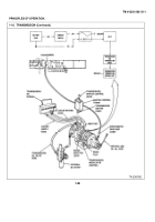
BATTERY PACK.
Consists of four, 12-volt, maintenance free batteries.
Two batteries are wired in parallel in each set.
Each set is connected in series for 24-volt
output.
Battery
pack
is used for both 12-volt
and 24-volt output.
IGNITION SWITCH.
Supplies 24-volt power to relay (RY-9), which in turn provides 12-volt power to electrical system,
including differential lockout indicator circuit.
RELAY (RY-9).
Energized by 24-volt power from ignition switch.
When energized, RY-9 supplies 12-volt power to circuit
breaker (CB-2).
LOCKOUT INDICATOR.
Illuminates when lockout switch is closed.
CIRCUIT BREAKER
(CB-2).
Protects electrical components of differential lockout circuit by opening when load exceeds
20 amperes.
May be manually reset by pressing CB-2 button in.
AIR MANIFOLD.
Routes air from reservoir to control valve.
LOCKOUT CHAMBER.
When air pressure is applied, chamber mechanically locks rear axle differential in place so that
drive is applied to both rear axles.
Without air pressure, differential applies drive to axle that offers least resistence.
CONTROL
VALVE.
When engaged, air pressure is applied to lockout rear differential action.
LOCKOUT SWITCH.
Normally open.
Closed by 60 psi air pressure to activate lockout indicator circuit.
1-64
Back to Top


