TM-9-2320-283-20-2 - Page 142 of 852
TM 9-2320-283-20-2
ELECTRICAL SYSTEM.
3-89.
ENGINE RETARDER FOOT SWITCH REPLACEMENT (Continued).
LOCATION/ITEM
ACTION
REMARKS
B.
INSTALLATION (Continued).
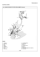
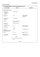
15.
Two nuts (11),
Install and tighten.
two lockwashers
(12), and two
screws (2).
16.
Wire (10) and
Install
Connect according to
wire (14)
identification tag
from step 7.
17.
Two lockwashers
Install and tighten.
(9) and two
nuts (13).
18.
Pedal (4)
Place in position and aline
with holes in item (7).
19.
Clevis pin (8)
Insert into item (7) and
through item (4).
20.
Washer (5) and new
Install
Bend end of item (6) to
cotter pin (6)
keep it from falling out.
21.
Floor mat (16)
Replace.
22.
Batteries
Connect
Refer to paragraph 3-120.
C.
OPERATIONAL CHECK.
23.
Engine
Start up
Refer to TM 9-2320-
283-10.
24.
Engine retarder
Push with foot
Verify operation.
(Refer
foot switch (15)
to TM 9-2320-283-10).
NOTE
Follow-on maintenance action required:
None.
3-514
Back to Top


