TM-9-2320-283-20-2 - Page 180 of 852
TM 9-2320-283-20-2
ELECTRICAL SYSTEM.
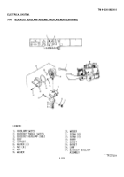
3-94. BLACKOUT MARKER LAMP ASSEMBLY REPLACEMENT (Continued).
LOCATION/ITEM
ACTION
REMARKS
E. BLACKOUT MARKER LAMP ASSEMBLY REASSEMBLY (Continued). I
23. Gasket (9)
Install in item (8).
24. Door assembly (8)
Align and install
Key way at bottom of item
and gasket (9)
(8).
25. Two screws (7)
Install and tighten.
F. BLACKOUT MARKER LAMP ASSEMBLY INSTALLATION. I
26. Spacer (4)
Align with mounting hole on
fender.
27. Blackout marker’
Install on spacer (4).
lamp assembly
Secure with item (5) and
(17)
item (6), and tighten.
28. Blackout marker
Connect to back of item (6).
lamp cable (3).
G. BLACKOUT MARKER LAMP ASSEMBLY OPERATIONAL CHECK. I
29. Operation switch
Set to blackout
Refer to TM 9-2320-283-
(2)
10.
30. Headlamp switch
a. Pull out to first
(1)
position.
b. Verify that blackout mark-
er lamp comes on.
NOTE
Follow-on maintenance action required:
Replace headlamp assembly
(para 3-91).
3-552
Back to Top


