TM-9-2320-283-20-2 - Page 50 of 852
TM 9-2320-283-20-2
ELECTRICAL SYSTEM.
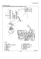
3-73. LEFT-HAND INSTRUMENT PANEL GAGE REPLACEMENT (Continued).
LOCATION/ITEM
ACTION
REMARKS
NOTE
The gages covered in the following procedure are identical as far as removal and installation; therefore, only
one is covered.
A. REMOVAL.
1
Four quarter-turn
Loosen.
screws (10).
2.
Hinged instrument
Lower.
panel (9).
3.
Wire connector
Remove
Tag for identification.
(1).
4.
Two nuts (3), two
Remove.
lockwashers
(4), and two flat
washers (5).
5.
Wire (8), wire
Remove
Tag for identification.
(11), and wire
Items (8) and (11) share
(15)
a common terminal type
connector.
6.
Two nuts (6)
Remove.
7.
Bracket (7),
Remove (7)
Note position Hold item (14) to pre-
two insulating
of two items (12)
vent it from falling out
inserts (12)
when removing item (7).
8.
Fuel gage (14)
Remove.
9.
Socket and bulb
Remove by turning a quarter
assembly (2)
turn to the left.
B. INSTALLATION. I
10. Socket and bulb
Install.
assembly (2).
11. Fuel gage (14)
Aline and insert in item (9).
3-422
Back to Top


