TM-9-2320-283-20-2 - Page 594 of 852
TM 9-2320-283-20-2
BRAKE SYSTEM.
3-166. FORWARD-REAR AXLE BRAKE CHAMBER REPLACEMENT (Continued).
LOCATION/ITEM
ACTION
REMARKS
C.
INSTALLATION.
NOTE
Before installing chamber assembly,
manually compress spring brake power
spring (TM 9-2320-283-10).
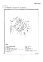
9.
Chamber assembly
Put in place on item (13).
(1).
10. Two nuts (9) and
Secure item (1) to item
Torque between 90 and
washers (10).
(13).
100 lb-ft.
11. Adjusting screw
Push in and turn until
(6).
item (7) can be installed
in item (11) and item (5).
12. Pin (7).
Install in item (11) and
item (5).
13. New pin (8).
Install in item (7).
14. Two elbows (2).
Install in item (1).
Put thread sealing tape
on pipe threads.
15. Tubes (3) and (4).
Install on two items (2).
16. Slack adjuster
Adjust.
Refer to paragraph
(5).
3-157.
17. Chamber assembly
Manually release spring
Refer to TM 9-2320-283-
(1).
brake power spring.
10.
18. Push rod (12)
Check angle.
An angle of 90° or more
and slack
is required.
If angle is
adjuster (5).
less than 90°, adjust
clevis (11) and recheck
angle.
NOTE
Follow-on maintenance action required:
Close air system draincocks and start
engine (TM 9-2320-283-10).
Check air system for leaks (para 3-8).
3-966
Back to Top


