TM-9-2320-285-10 - Page 15 of 121
TM 9-2320-285-10
1-15.
ELECTRICAL SYSTEM (Continued)
a.
Vehicle Lights_(continued).
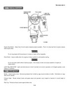
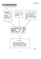
Dash Lights - Post-type lights illuminate controls when headlights are on; rotate headlight switch clockwise to decrease
brightness, counterclockwise to increase brightness.
Gage Lights - Internal lights illuminate gage faces and pointers when headlights are on; headlight switch controls
brightness: counterclockwise to brighten, clockwise to dim.
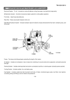
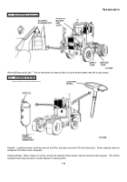
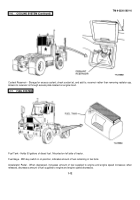
CAB REAR FLOOD LIGHT - Incandescent lamp and clear lens, mounted on rear cab guard, illuminates fifth wheel area.
Turned ON and OFF with appropriate FLOOD LIGHT switch, or when transmission is shifted into reverse during tractor
operation.
LEFT and RIGHT ROOF FLOOD LIGHTS - Two sealed-beam type lamps, mounted on rear of cab roof, illuminate
container numbers when tractor drives in aisles at night.
Turned ON and OFF by appropriate FLOOD LIGHT Switches.
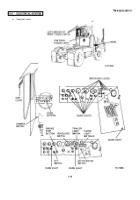
FLOOD LIGHT Switches - Three separate FLOOD LIGHT switches control three flood lights.
Push up for ON, down for
OFF.
Cab Light - Incandescent lamp with cover mounted on cab roof, left hand side.
Controlled by cab light switch located next
to light; push up to turn ON, down to turn OFF.
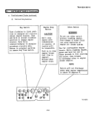
Headlight Switch Pulling out to notched position turns on clearance, dash and gage, side marker, and front and rear
parking lights.
In second notched position, also turns on headlights.
When electrical cable is connected between tractor
and trailer, first and second notched positions also turn on trailer clearance, parking, and side marker lights.
Dimmer Switch - Foot-operated switch installed in cab floor, left hand side.
Press with left foot to select head light high
beam or low beam.
Trailer Light Switch - With 12V electrical cable connected to trailer, delivers power to trailer interior lights, independent of
trailer exterior lights; pull out to turn ON, push in to turn OFF.
b.
Horn.
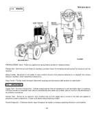
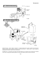
Horn - Electric horn operated by pressing horn button on steering wheel.
Mounted on front frame crossmember.
Horn Button - Spring loaded button located at center of steering wheel.
Horn sounds when button is pressed (unless key
switch is in OFF position), turns off when button is released.
c.
Switches and Indicator Lights.
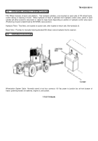
Engine Stop Button - Stops fuel flow to engine when pressed.
Release when engine stops; to restart engine, key switch
must be used to crank starter.
1-10
Back to Top

