TM-9-2320-304-14-P - Page 29 of 1320
TM 9-2320-304-14&P
iii
LIST OF ILLUSTRATIONS
Figure
Title
Page
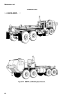
1-1
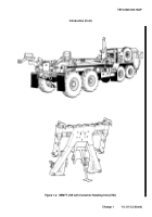
HEMTT Load Handling System Vehicle
1-2
...........................................
2-1
LHS Controls and Indicators
2-2
.....................................................
3-1
Lubrication Points
3-2
...............................................................
4-1
General Tightening Sequences
4-149
....................................................
4-2
Hydraulic Lines -- M1120 Vehicle
4-236
.................................................
5-1
General Tightening Sequences
5-81
....................................................
FO-1
LHS Wiring Schematic
FP-1
...........................................................
FO-1.1 LHS-CHU Wiring Schematic
FP-4.1
.....................................................
FO-2
Chassis Electric Schematic
FP-5
.......................................................
FO-2.1 CHU Chassis Electric Schematic
FP-6.1
..................................................
FO-3
Hydraulic Schematic
FP-7
.............................................................
LIST OF TABLES
Number
Title
Page
1-1
Equipment Data
1-8
.................................................................
1-2
Load Classification
1-13
..............................................................
2-1
Operator’s Preventive Maintenance Checks and Services (Before)
2-7
...................
2-2
Operator’s Preventive Maintenance Checks and Services (After)
2-8
.....................
2-3
Operator’s Preventive Maintenance Checks and Services for CHU (After)
2-8.1
............
3-1
Fault Symptom Index
3-4
............................................................
3-2
Troubleshooting
3-5
.................................................................
4-1
Unit Level Preventive Maintenance Checks and Services (PMCS)
4-6
...................
4-2
Load Handling System Fault Index
4-12
...............................................
4-2.1
Container Handling Unit (CHU) Fault Index
4-12
......................................
4-3
Load Handling System (LHS) Troubleshooting
4-13
.....................................
4-3.1
Container Handling Unit (CHU) Troubleshooting
4-142.1
..................................
4-4
Recommended Flats Rotation
4-148
.....................................................
4-4.1
CHU Control Box Wiring
4-170.5
.........................................................
4-5
Proximity Switch Wire Positions
4-172
..................................................
5-1
Load Handling System Fault Index
5-4
...............................................
5-2
Direct Support/General Support Troubleshooting
5-5
...................................
5-3
Recommended Flats Rotation
5-80
.....................................................
H-1
Wooden Blocks
H-1
..................................................................
J-1
Torque Limits For Wet Flange Nuts
J-2
...............................................
J-2
Torque Limits For Wet Socket Head Cap Screws
J-2
...................................
J-3
Torque Limits For Dry Fasteners
J-4
.................................................
J-4
Torque Limits For Wet Fasteners
J-5
.................................................
J-5
Torque Limits For 37-Degree Flare Hose Connections
J-6
...............................
J-6
Torque Limits For 45-Degree Flare Hose Connections
J-6
...............................
J-7
Torque Limits For ORS Preformed Packing Face Seal Hose Connections
J-7
..............
J-8
Torque Limits For NPSM Swivel Connections
J-7
......................................
K-1
Mandatory Replacement Parts
K-1
....................................................
Change 1
Back to Top

